Plasma display panel

a technology of plasma display panel and display panel, which is applied in the direction of gas discharge electrodes, gas discharge vessels/containers, gas discharge tubes, etc., can solve the problems of short circuit of electrodes, lowering the density of the protective layer, and reducing the firing voltage of the plasma display panel. , to achieve the effect of improving the contrast and jitter characteristics and lowering the firing voltage of the plasma display panel

Inactive Publication Date: 2007-06-07
LG ELECTRONICS INC
View PDF5 Cites 38 Cited by
  • Summary
  • Abstract
  • Description
  • Claims
  • Application Information

AI Technical Summary

Benefits of technology

[0014] Another object of the present invention is to provide a protective layer that lowers the firing voltage of a plasma display panel comprising the protective layer and that improves the contrast and jitter characteristics of the plasma display panel.

Problems solved by technology

At this time, short circuiting of the electrodes may be caused by metal elements, such as sodium (Na).
However, the protective layer of the conventional plasma display panel has the following problems.
Firstly, since the magnesium oxide crystal particles constituting the protective layer have a non-uniform diameter, the density of the protective layer is lowered and the crystal is not sufficiently grown.
Secondly, since the magnesium oxide crystal particles constituting the protective layer have a non-uniform size, impurities, e.g., moisture and impurity gases, are attached to the surface of the protective layer.
These impurities impede the discharge of the plasma display panel, and cause low contrast and high firing voltage of the plasma display panel, making the circuit structure complicated.
This complicated circuit structure may incur considerable costs.

Method used


Image

  • Plasma display panel
  • Plasma display panel
  • Plasma display panel

Examples


Embodiment Construction

[0022] Reference will now be made in detail to the preferred embodiments of the present invention, examples of which are illustrated in the accompanying drawings. Wherever possible, the same reference numbers will be used throughout the drawings to refer to the same or like parts.

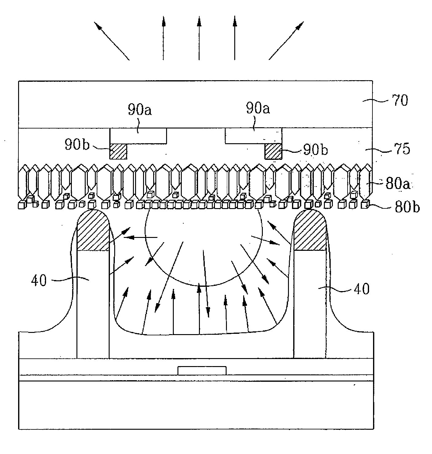
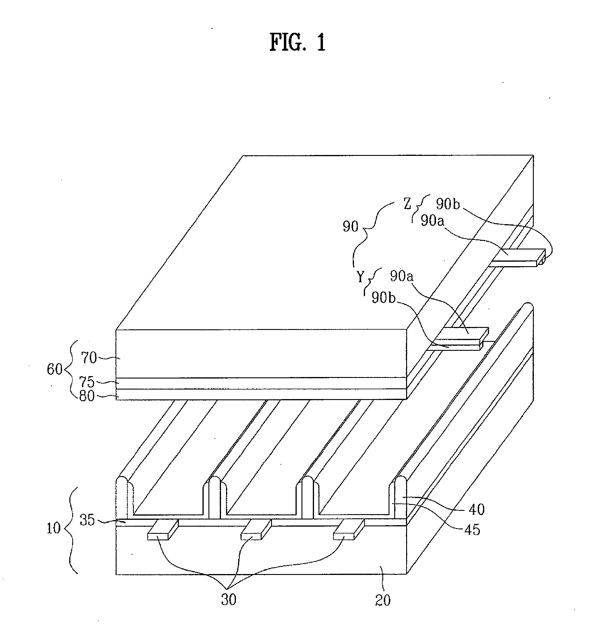
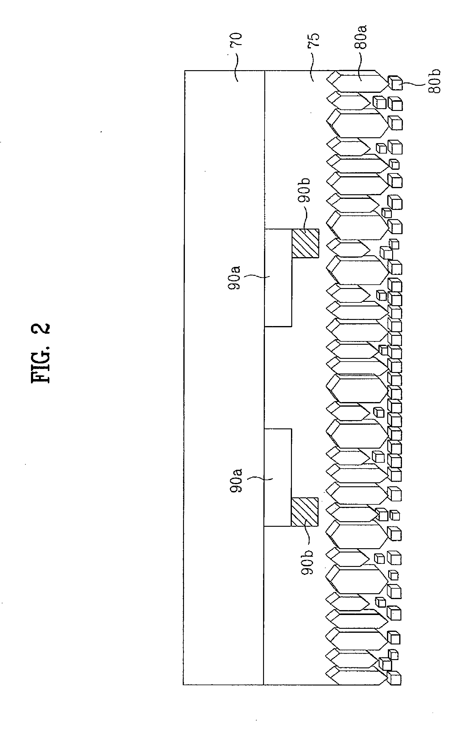
[0023] The present invention provides a plasma display panel comprising a bilayered protective layer. Hereinafter, a layer formed on one surface of an upper dielectric layer is referred to as a ‘first protective film’, and a layer formed on the first protective film is referred to as a ‘second protective film’. The first protective film is composed of densely-packed columnar magnesium oxide crystal particles and acts to protect the dielectric layer. The second protective film is composed of hexahedral magnesium oxide crystal particles spaced apart from each other at intervals, making the entire surface of the protective layer irregular. The irregular surface of the protective layer can contribute to an inc...


PUM


Abstract

Disclosed is a plasma display panel with improved discharge characteristics. The plasma display panel comprises an upper panel and a lower panel integrally joined to the upper panel through barrier ribs wherein the upper panel includes a dielectric layer, a first protective film formed on one surface of the dielectric layer and composed of columnar magnesium oxide crystal particles, and a second protective film formed on the first protective film and composed of hexahedral magnesium oxide crystal particles.

Description

[0001] This application claims the benefit of Korean Patent Application No.10-2005-0104987, filed on Nov. 03, 2005 which is hereby incorporated by reference as if fully set forth herein. BACKGROUND OF THE INVENTION [0002] 1. Field of the Invention [0003] The present invention relates to a plasma display panel, and more particularly, to a protective layer of a plasma display panel. [0004] 2. Discussion of the Related Art [0005] Plasma display panels comprise an upper panel, a lower panel, and barrier ribs formed between the upper and lower panels to define discharge cells. A major discharge gas, such as neon, helium or a mixed gas thereof, and an inert gas containing a small amount of xenon (Xe) are filled within the discharge cells. When a high-frequency voltage is applied to produce a discharge in the discharge cells, vacuum ultraviolet rays are generated from the inert gas to cause phosphors present between the barrier ribs to emit light, and as a result, images are created. Such ...

Claims


Application Information

Patent Timeline
Patent Type & Authority Applications(United States)
IPC IPC(8): H01J17/49H01J11/22H01J11/24H01J11/34H01J11/40
CPCH01J11/12H01J11/40
Inventor LEE, IN YOUNG
Owner LG ELECTRONICS INC
Why Eureka
Try Eureka