Switch-capacitor loop filter for phase lock loops

Active Publication Date: 2007-06-07
REALTEK SEMICON CORP
View PDF12 Cites 20 Cited by
  • Summary
  • Abstract
  • Description
  • Claims
  • Application Information

AI Technical Summary

Benefits of technology

[0009] What is needed is a method to alleviate the non-uniform sampl

Problems solved by technology

The non-uniform sampling is a highly nonlinear phenomenon and results in increase of phase noise in the PLL output.
This problem, however, is rarely discussed or addressed in prior art, because in steady state the frequency/phase of the VCO has been tracking well with that of the reference clock, the UP/DN pulses are thus very short, and therefore the non-uniform sampling problem is usually negligible.
This problem, however, becomes an important source of performance degradation in an fractional-N frequency synthesizer.
If N is a fractional number, a straight implementation using a counter with a fixed divisor valu

Method used


Image

  • Switch-capacitor loop filter for phase lock loops
  • Switch-capacitor loop filter for phase lock loops
  • Switch-capacitor loop filter for phase lock loops

Examples


Embodiment Construction

[0031] In the present disclosure, numerous specific details are provided, such as examples of apparatus, circuits, components, and methods, to provide a thorough understanding of embodiments of the invention. Persons of ordinary skill in the art will recognize, however, that the invention can be practiced without one or more of the specific details in various embodiments. In other instances, well-known details are not shown or described to avoid obscuring aspects of the invention.

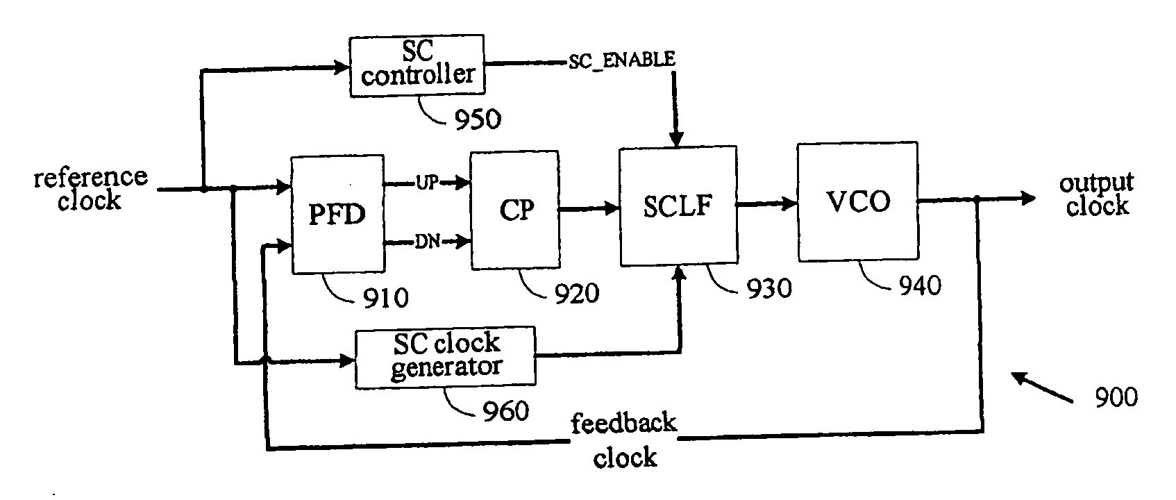
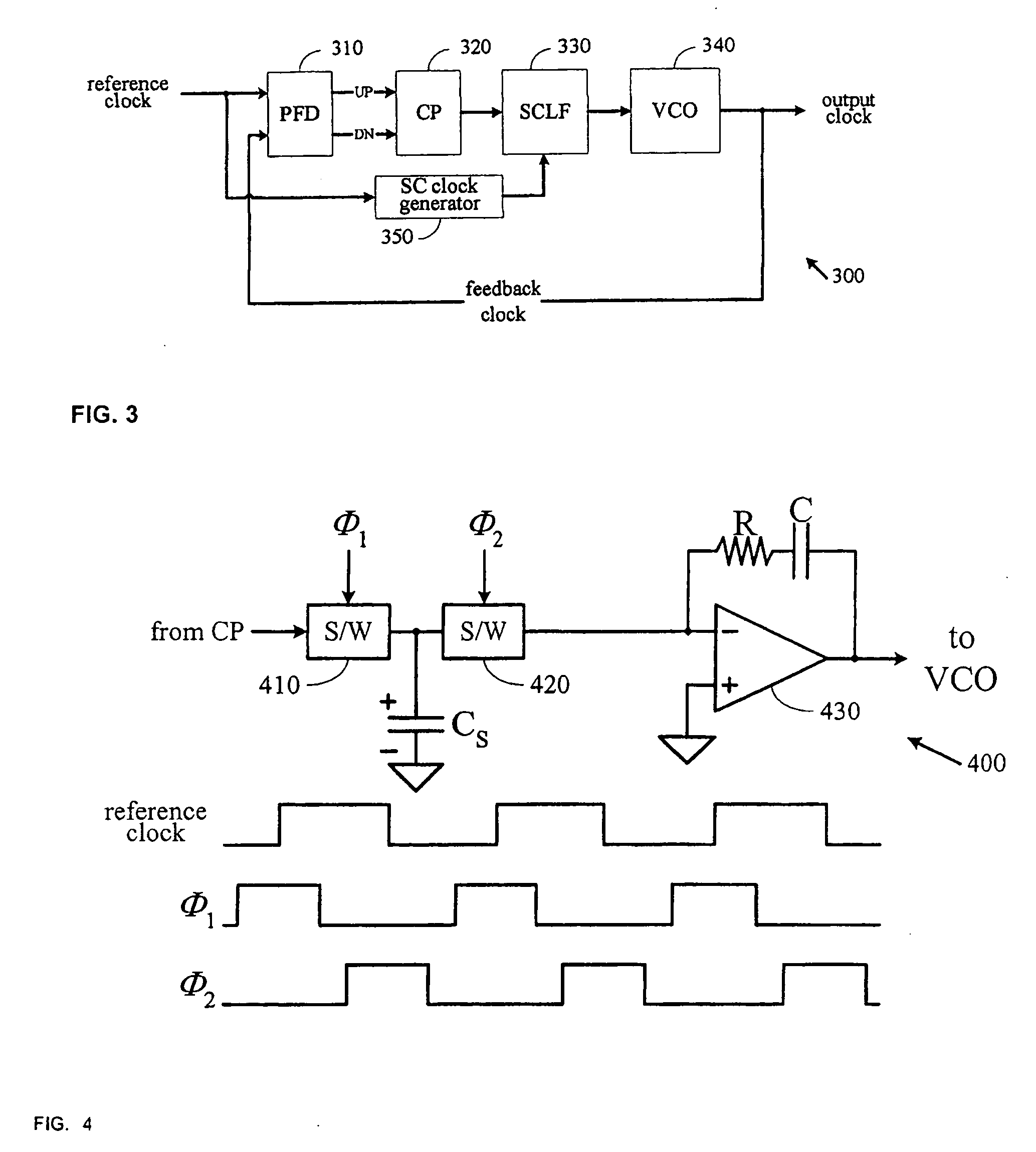
[0032]FIG. 3 depicts a functional block diagram of a circuit 300, e.g., a Phase Lock Loop, in accordance with an embodiment of the present invention. In this embodiment, a phase / frequency detector (PFD) 310 compares the phase of an input signal (e.g., a reference clock) with a feedback signal (e.g., a feedback clock). The phase difference between these two signals is represented by an output from the PFD 310. In the illustrated embodiment, the output from PFD 310 includes two logical signals, an UP signal ...


PUM


Abstract

A switch-capacitor loop filter is used to generate a control voltage for a voltage-controlled oscillator (VCO) in a phase lock loop (PLL). The switch-capacitor circuit works in a multi-phase manner including at least two non-overlapping phases: a sampling phase and a transfer phase. During the sampling phase, the current representing the phase difference between the reference clock and the feedback clock of the PLL is integrated by a sampling capacitor. During the transfer phase, the charge stored on the sampling capacitor is transferred to a load capacitor. The timing for controlling the switch-capacitor function is derived from the reference clock.

Description

BACKGROUND OF THE INVENTION [0001] 1. Field of the Invention [0002] The present invention relates generally to phase lock loops, and more particularly, but not exclusively, to methods and apparatus for a phase lock loop with a switch-capacitor loop filter. [0003] 2. Description of Background Art [0004] As depicted in FIG. 1, a typical phase lock loop (PLL) based frequency synthesizer 100 includes a phase / frequency detector (PFD) 110, a charge pump (CP) circuit 120, a loop filter (LF) 130, and a voltage controlled oscillator (VCO) 140. The PFD 110 compares a reference clock and a feedback clock generated by the VCO to determine the phase difference. The PFD 110 outputs two logical signals, UP and DN signals to represent the phase difference between the two clocks. Each time a phase comparison is made, an UP signal pulse or a DN signal pulse is generated. If the reference clock is leading the feedback clock (in terms of clock phase), an UP pulse is generated. Otherwise, a DN pulse is ...

Claims


Application Information

Patent Timeline
IPC IPC(8): H03L7/00
CPCH03L7/0891H03L7/093H03L7/1976
Inventor LIN, CHIA-LIANGCHOU, GERCHIHKUAN, CHI-KUNG
Owner REALTEK SEMICON CORP
Why Eureka
Try Eureka