Method for operating flue gas purification system
a technology of flue gas purification and flue gas, which is applied in the direction of emission prevention, separation processes, lighting and heating apparatus, etc., can solve the problems of weak x/sub>reduction reaction, insufficient burning of coal, and degradation of catalysts, etc., and achieves short time, non-uniform denitration reaction and other problems.
Active Publication Date: 2022-09-13
MITSUBISHI HEAVY IND LTD
View PDF21 Cites 0 Cited by
- Summary
- Abstract
- Description
- Claims
- Application Information
AI Technical Summary
Benefits of technology
The present invention provides a method for inhibiting the adhesion of unburned combustible contents of oil fuel to a denitration catalyst and uniformly increasing the temperature of the denitration equipment during the boiler startup by oil combustion. This method reduces strain and nonuniformity of denitration reaction and helps in starting the denitration treatment of flue gas without much delay from the boiler startup.
Problems solved by technology
Since coal has low combustibility, when the conditions such as the internal temperature of a boiler furnace are not right, coal cannot be sufficiently burned.
In the denitration equipment shortly after the startup, however, NOx reduction reaction can proceed weakly because the temperature of catalytic layers is low.
In addition, moisture contained in the exhaust gas can build up condensation in the catalytic layers, leading to degradation of the catalyst.
Method used
View moreImage
Smart ImageViewing Examples

Examples
example 1
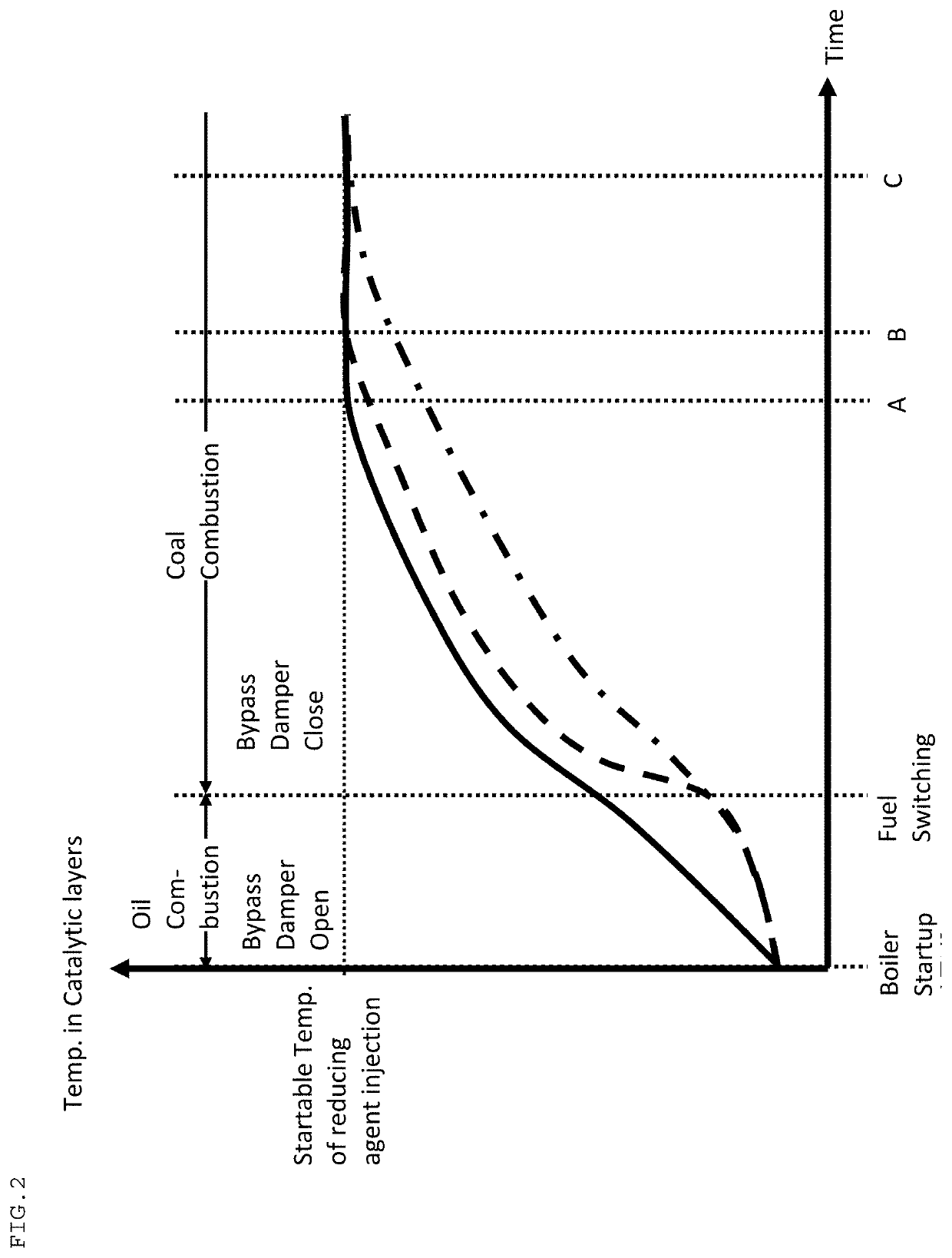
[0027]The solid line in FIG. 2 shows an example of changes in temperature of catalytic layers when the operation method of the present invention was carried out in the flue gas purification system shown in FIG. 1. The temperature of catalytic layers was increased at an almost constant rate from the temperature at the boiler startup to the temperature which injection of a reducing agent can be started at. Even when closing the bypass damper after switching fuels (after about 200 minutes of the boiler startup), the rate of temperature increase of catalytic layers was not rapidly changed. Time (A) for the catalytic layers to reach a temperature at which injection of ammonia can be started was about 800 minutes after the boiler startup.
Login to View More PUM
 Abstract
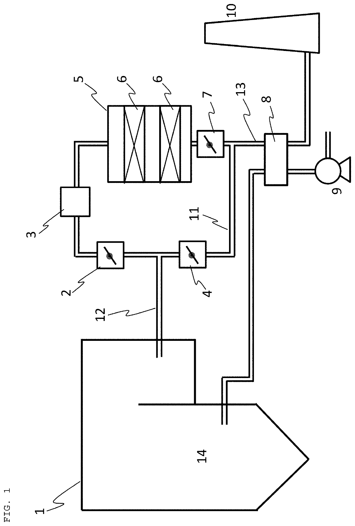
A method for operating a flue gas purification system, comprising, in the flue gas purification system, equipped with a boiler which can burn oil fuel and coal fuel either simultaneously or switching therebetween, a denitration equipment having a reducing agent injector and a catalytic reactor, an inlet flue to guide flue gas discharged from the boiler to the denitration equipment, an outlet flue to guide flue gas discharged from the denitration equipment, a bypass flue which can guide flue gas from the inlet flue to the outlet flue so as to bypass the denitration equipment, and a bypass damper, opening the bypass damper and burning oil fuel in the boiler being in condition not yet suitable for coal combustion to allow the flue gas discharged from the boiler to dividedly flow to the denitration equipment and the bypass flue, switching the oil fuel to coal fuel when the boiler is in condition suitable for coal combustion to burn the coal fuel in the boiler, closing the bypass damper after switching the oil fuel to the coal fuel, and then injecting a reducing agent when the catalytic reactor is in condition suitable for a denitration reaction.
Description
TECHNICAL FIELD[0001]The present invention relates to a method for operating a flue gas purification system. More specifically, the present invention relates to a method for operating a flue gas purification system, which can inhibit unburned combustible contents of oil fuel from adhering to a denitration catalyst at the boiler startup by oil combustion as well as can increase temperature of a denitration equipment more uniformly in a shorter time.BACKGROUND ART[0002]In thermal power plants, the daily start stop (DDS) operation, the weekly start stop (WSS) operation or the like is carried out depending on electric demand. Since coal has low combustibility, when the conditions such as the internal temperature of a boiler furnace are not right, coal cannot be sufficiently burned. Therefore, in a coal fired boiler, oil fuel with high combustibility such as light oil or heavy oil is fed to the boiler furnace to start combustion, and oil fuel can be switched to coal fuel when the conditi...
Claims
Login to View More Application Information
Patent Timeline
 Patent Type & Authority Patents(United States)
IPC IPC(8): F23J15/00B01D53/94F23C1/02B01D53/86F23L15/02
CPCF23J15/003B01D53/8631B01D53/8696B01D53/9431F23C1/02F23J15/006B01D2258/0283F23J2219/10F23J2900/11001F23L15/02F23N2237/20F23J2215/10Y02E20/34
Inventor II, SHINYAHIROTA, AKIRASHISHIDO, SATORUYASHIRO, KATSUHIROYOSHIMURA, HIROYUKISHIMIZU, NOBUAKI
Owner MITSUBISHI HEAVY IND LTD