Optical disk device, semiconductor laser drive device and optical pickup device

a technology of optical disk and optical pickup, which is applied in the direction of optical beam sources, instruments, data recording, etc., can solve the problems of detriment to the affection of data recorded on the optical disk, and achieve the effects of reducing waveform distortion, reducing power loss, and low waveform distortion

Inactive Publication Date: 2007-06-07
HITACHI LTD +1
View PDF7 Cites 2 Cited by
  • Summary
  • Abstract
  • Description
  • Claims
  • Application Information

AI Technical Summary

Benefits of technology

[0012] Accordingly, the laser drive device having the laser current output circuit and a high frequency superposing circuit should be driven with a low waveform distortion and a lower power loss over a wide band from 1 to 500 MHz.
[0013] Thus, in view of the above-mentioned requisites, the present invention is to provide the following method in order to solve the problems. That is, an object of the present invention is to control the output impedance of the laser drive device and the line impedance of the signal transmission line between the laser drive device and the semiconductor laser so as to aim at making impedance matching in a predetermined frequency band, in order to reduce waveform distortion and lower power loss caused b

Problems solved by technology

When a waveform of a signal for driving the laser is distorted so as to affect a laser current, the energy

Method used


Image

  • Optical disk device, semiconductor laser drive device and optical pickup device
  • Optical disk device, semiconductor laser drive device and optical pickup device
  • Optical disk device, semiconductor laser drive device and optical pickup device

Examples


embodiment 1

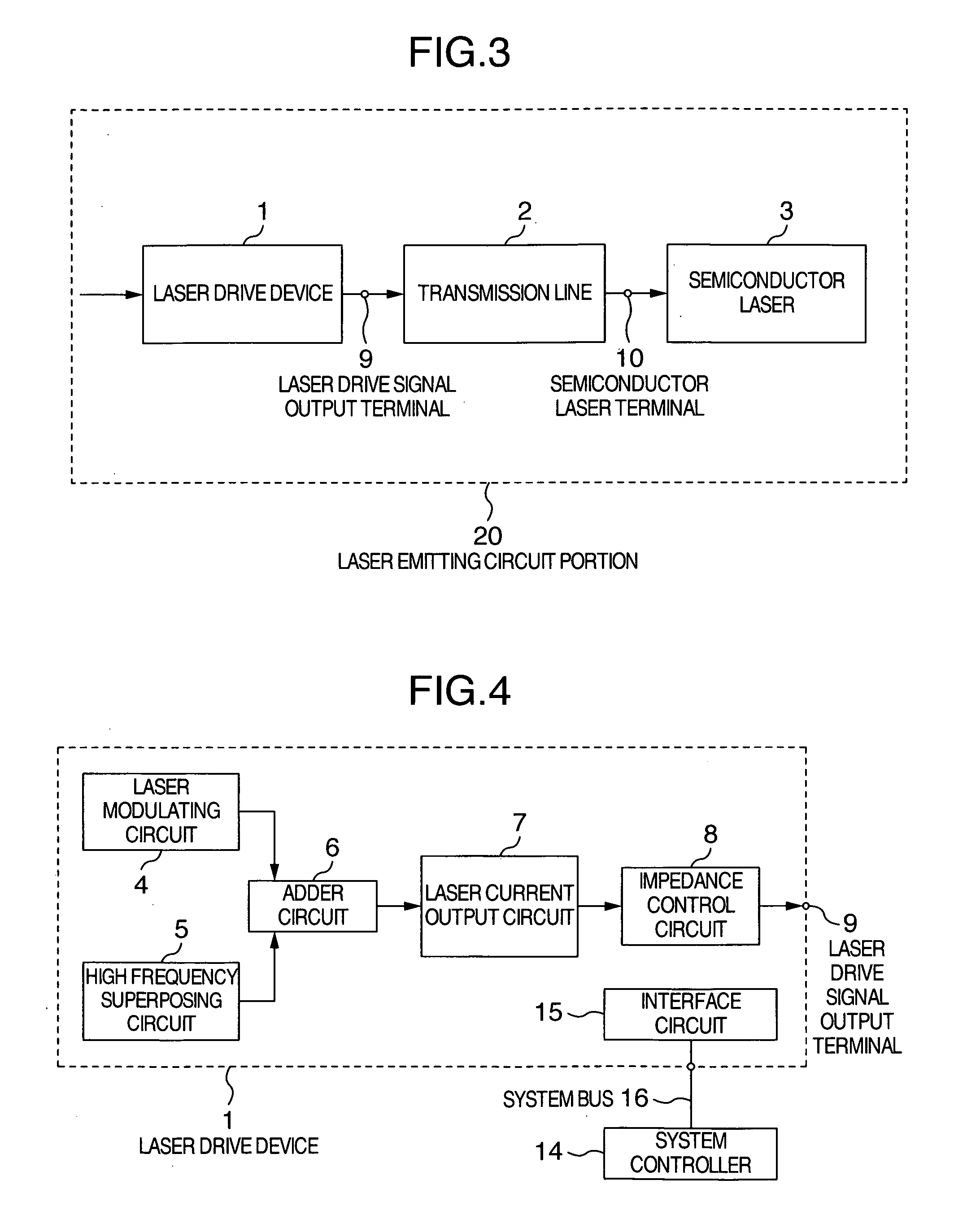
[0028] A first embodiment of the present invention will be explained with reference to FIG. 3.

[0029] Referring to FIG. 3 which is a block diagram illustrating a laser emitting circuit portion in an optical pickup in an optical disk device according to the present invention, the laser emitting circuit portion is composed of a laser drive device 1, a transmission line 2 and a semiconductor laser 3, which are electrically connected with one another by signal lines in a flexible print circuit board arranged on an outer surface of the optical pickup. The transmission line 2 is adapted to feed a laser drive signal outputted from the laser drive device 1, to the semiconductor laser 3. The transmission line 2 is a signal wiring part between a laser drive signal output terminal 9 of the laser drive device 1 and a semiconductor laser terminal 10 of the semiconductor laser 3.

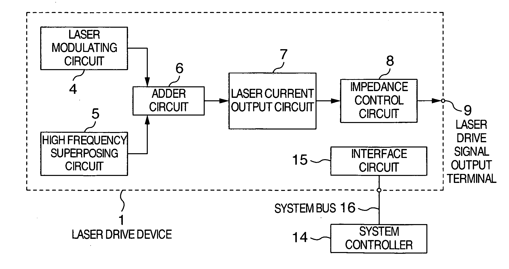
[0030] Referring to FIG. 4 which is a block diagram illustrating a configuration of a laser drive device in an embodim...


PUM


Abstract

Provided is a device which can reduce waveform distortion of a laser drive signal caused by impedance mismatching between a laser drive device and a semiconductor laser over a wide band, and which can enhance the power efficiency of higher frequency superposition during reproduction. The output impedance of the laser drive device and the line impedance of a transmission line between the laser drive device and the semiconductor laser are controlled so as to attain impedance matching in a predetermined frequency band. Specifically, the laser drive device is provided thereto with an output impedance control circuit for controlling the output impedance in order to change the impedance of a laser drive device output terminal, depending upon an impedance of the semiconductor laser and an impedance of the transmission line.

Description

INCORPORATION BY REFERENCE [0001] The present application claims priority from Japanese application JP2005-347419 filed on Dec. 1, 2005, the content of which is hereby incorporated by reference into this application. BACKGROUND OF THE INVENTION [0002] The present invention relates to an optical pickup device emitting a laser beam so as to carry out recording and reproduction onto and from an optical disk, a semiconductor laser drive device used in the optical pickup device, and an optical disk device using the above-mentioned devices, for carrying out recording and reproduction onto and from an optical disk. [0003] A laser drive device has a laser current output circuit which outputs a modulated laser current for changing the state of a recording layer of an optical disk by energy of a laser beam emitted from an optical pickup in order to record data onto an optical disk. [0004] Further, when data is reproduced from the optical disk, the laser drive device has a high-frequency super...

Claims


Application Information

Patent Timeline
IPC IPC(8): G11B7/00
CPCG11B7/126
Inventor FUKUSHIMA, AKIO
Owner HITACHI LTD
Why Eureka
Try Eureka