Narrow band laser with wavelength stability

a narrow band laser and wavelength stability technology, applied in the direction of laser details, optical resonator shape and construction, semiconductor lasers, etc., can solve the problems of material thermal expansion and change in cavity length, and achieve the effects of low cavity loss, high power operation, and small cavity siz

Inactive Publication Date: 2007-06-07
NEW FOCUS +1
View PDF7 Cites 16 Cited by
  • Summary
  • Abstract
  • Description
  • Claims
  • Application Information

AI Technical Summary

Benefits of technology

[0011] In accordance with this disclosure there is provided an external cavity laser system intended for (but not limited to) output of a fixed single (narrow band) wavelength light beam. The laser system includes as the reflector a self-aligning retroreflector such as a roof-top prism retroreflector or corner-cube type retroreflector. These provide self-alignment of the retroreflector, thus making the laser cavity insensitive to cavity end mirror tilting. They also provide low cavity loss and relatively small cavity size making the laser advantageous over other types of laser systems in both total power consumption and high power operation at a single output wavelength.
[0012] Also provided is a thermal compensation aspect making the cavity length of the laser system insensitive to temperature variation and thereby providing more robust mode-hop free operation. This includes using retroreflector position movement by thermal expansion of its mounting material thereby fully employing the self-alignment feature of the retroreflector. This has been found to reduce critical tolerances and adjustments, thereby improving manufacturability and reducing cost.
[0013] Even for a fixed wavelength laser, mode-hop could occur if the cavity length experiences a change over an amount of a fraction of wavelength, which is usually only a few hundred nanometers. The cavity length change can result from material thermal expansion, attachment relaxation, environmental disturbance, etc. The present laser system makes the compact cavity possible and in addition to that, the thermal compensating cavity and components insensitive to environmental disturbance are employed to make the cavity more robust.

Problems solved by technology

The cavity length change can result from material thermal expansion, attachment relaxation, environmental disturbance, etc.

Method used


Image

  • Narrow band laser with wavelength stability
  • Narrow band laser with wavelength stability
  • Narrow band laser with wavelength stability

Examples


Embodiment Construction

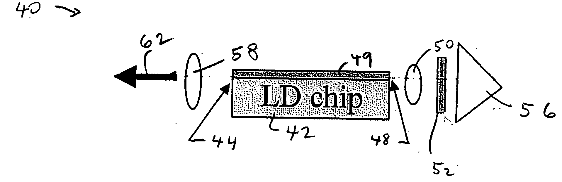
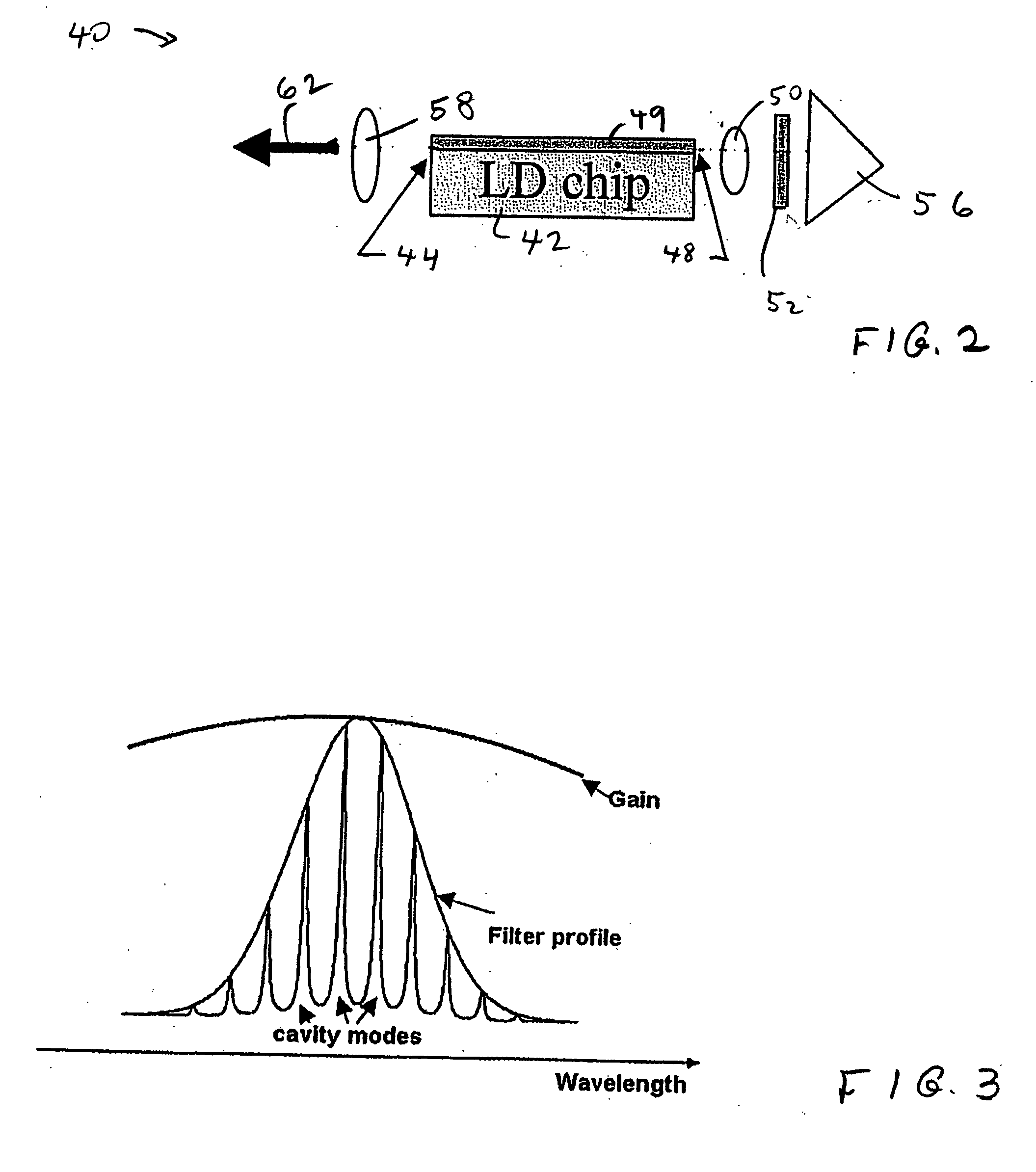
[0018]FIG. 2 shows in somewhat simplified form a laser system in accordance with this disclosure. It is to be understood that this is similar to FIG. 1 in the sense of omitting the associated mounting structures, power supply, etc. for simplicity of illustration. These are generally conventional, and of a type well known in the field. See, for instance, Zorabedian et al., U.S. Pat. No. 6,282,215, cited above, FIGS. 1A and 1B showing typical mounting systems. In some respects, the present mounting system is other than conventional, as further described below. FIG. 2 shows the external cavity diode-type laser. The laser diode (LD chip) 42 is conventional, for instance, part number SDL5400, purchased from JDS Uniphase. In one embodiment laser diode 42 outputs wavelengths of light in the range of 805 nm to 815 nm at output power of 0.2 watts. The power supply for laser diode 42 is conventional and not shown here. Such laser diodes are a type of solid state laser produced typically by se...


PUM


Abstract

An external cavity diode laser system includes a thin film filter. The output facet of the laser diode is coated with a partial reflection coating and the cavity side facet is coated with an anti-reflection coating. A roof-top prism or corner cube retroreflector serves as the laser cavity end reflector and provides stability of the wavelength of the output over time. The laser cavity lies between the partial reflective coated facet of the laser diode and retroreflector. A collimating lens and a thin film filter are located between the end reflector and the laser diode cavity side facet. The lasing wavelength can be adjusted during either manufacture or operation by tilting the filter. Also included is thermal compensation in the mounting for the retroreflector to compensate for thermal movement of the laser system cavity.

Description

FIELD OF THE INVENTION [0001] This disclosure is directed to optical devices including external cavity semiconductor lasers and other type of lasers, and in particular, to external cavity lasers having stabilized nominally single wavelength (narrow band) outputs. BACKGROUND [0002] External cavity semiconductor lasers are well known. See Scobey et al., U.S. Pat. No. 6,115,401, assigned to Corning OCA Corporation, incorporated by reference herein in its entirety. In external cavity diode lasers which are typical of such devices, an optical cavity extends between a first facet (surface) of a semiconductor diode laser (laser diode) and an external reflector, defining the laser cavity ends. The opposite facet of the semiconductor diode laser, between the diode laser and the first facet, typically carries a partial reflection coating to allow light to escape the diode laser with minimum reflection. [0003] Such laser systems have been used extensively as transmitters for fiber-optic commun...

Claims


Application Information

Patent Timeline
Patent Type & Authority Applications(United States)
IPC IPC(8): H01S3/08
CPCH01S3/08059H01S3/1062H01S5/02208H01S5/02248H01S5/02415H01S5/02438H01S5/06837H01S5/141H01S5/02325
Inventor WANG, WEIZHIZHANG, GUANGZHI Z.LE, LAM T.
Owner NEW FOCUS
Why Eureka
Try Eureka