Elliptically polarizing plate and method of producing the same

a technology of elliptical polarizing plate and elliptical polarizing plate, which is applied in the direction of polarizing elements, thin material handling, instruments, etc., can solve the problems of low yield, large loss of materials during the operating process, and increased cost, so as to reduce thickness and improve production efficiency. , the effect of good yield

Inactive Publication Date: 2007-06-07
SUMITOMO CHEM CO LTD
View PDF14 Cites 19 Cited by
  • Summary
  • Abstract
  • Description
  • Claims
  • Application Information

AI Technical Summary

Benefits of technology

[0019] The present invention has been achieved as a result of studying the solutions of problems in conventional techniques as described above, and an object of the invention is to provide an elliptical polarizing plate that is good in production efficiency and yield and suitable for reducing the thickness of the polarizing plate, and a method of producing the elliptical polarizing plate.
[0023] An elliptically polarizing plate of the invention can be formed in a roll form, and also provides both of a linear polarizing plate and a compensation film, constituting the elliptically polarizing plate, in a seamless form, so the elliptically polarizing plate is good in production efficiency and yield and also suitable for reducing thickness of a variety of display apparatuses, including the case of cutting elliptically polarizing plate to sheet materials.

Problems solved by technology

In such method, the operating processes are complicated, the loss of materials during the operating process is great, and the cost tends to be increased.
In addition, yield may not be advantageous, and the continuation of the laminating step may not be easy.
Thus, it is possible to some extent to carry out the continuation of the laminating step, the improvement of yield, and the reduction of loss of material, but the method may not increase production capacity.
Moreover, the method has a limit to cost reduction.
However, a sufficient solution has not been found in either case from the viewpoints of continuation of the laminating step, improvement of yield, reduction of material loss, and cost reduction.
However, this method needs the process of joining the bias cut plates, thereby not increasing production capacity, and lowering yield due to low precision of angle control when it is laminated with a compensation film, leading to a large increase in cost.
Additionally, use of, for example, an adhesive tape on the site to be joined may cause problems in that the site is lost in a product, the joint generates a step height caused by the adhesive tape, producing a cause of the failure of joining the linear polarizing plate, and the like.
Furthermore, even though a rolled elliptically polarizing plate is produced, the joint remains on the roll, and thus cutting out the elliptically polarizing plate without a joint is extremely difficult when a sheet-like elliptical polarizing plate with a large size is cut out.
This method, however, involves cutting and taking out a rectangular sheet material in such a way that each of two sides contacted by the rectangle has a specific angle relative to the stretch axis, so the area remaining not cut is inevitably large.
This area is directly a loss of an expensive optical film and thus may increase cost.
Furthermore, as in JP6-289221A mentioned above, cutting out the elliptically polarizing plate without a joint is extremely difficult when a sheet-like elliptical polarizing plate with a large size is cut out.
As in JP 6-289221 A and JP6-300918A, in the production of an elliptical polarizing plate, a method that involves cutting out one of the optical films at a specific angle in the form of a sheet, and arranging it in a specified position so as to be capable of roll to roll laminating, that is, to be capable of forming in the form of a roll and laminating the longitudinal direction portions to each other may cause a problem in a joint.
This method, however, needs an apparatus for producing a cylindrical film (blow molder), makes it difficult to create an angle with high precision when the cylindrical stretch film is continuously cut at a specific angle, and makes the processes more complicated than the processes in the case of a compensation film fabricated by stretching a rolled film, leading to a considerable increase in cost.
The method, however, needs to stretch the long cellulose acetate film on the slant.
Slant-stretching renders it difficult to stretch at a specific angle with high precision as compared with vertical uniaxial stretch or horizontal uniaxial stretch and thus productivity is low resulting in increasing cost.
This method, however, needs to slant-stretch a polyvinyl alcohol film.
Slant-stretching makes it difficult to carry out stretching at a specific angle with high precision as compared with vertical uniaxial stretch or horizontal uniaxial stretch, thereby lowering production and increasing cost.
As described above, it is presently difficult to produce an elliptical polarizing plate by means of roll to roll laminating processing in conditions of satisfying all the respects of continuation of the laminating process, improvement of yield, reduction of material loss, and reduction of cost.

Method used


Image

  • Elliptically polarizing plate and method of producing the same
  • Elliptically polarizing plate and method of producing the same
  • Elliptically polarizing plate and method of producing the same

Examples


example 1

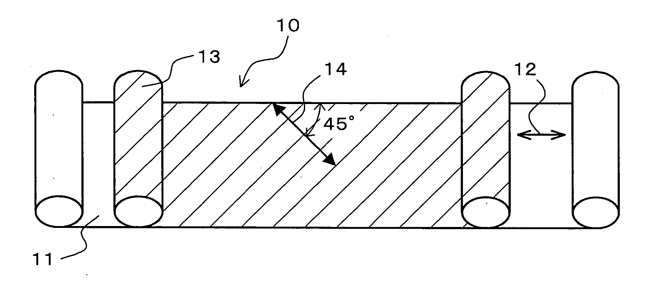
[0074] (a) Rolled Quater-Wave Plate

[0075] A rolled Quater-Wave plate was prepared that has a slow axis in the direction inclined at an angle of 45° within a film face relative to the longitudinal direction of a rolled transparent substrate, with polymerizing liquid crystal compounds being orientated along a single face of the rolled substrate produced by saponifying a triacetyl cellulose film having a thickness of 80 μm (“Fujitac TF80UL” available from Fuji Photo Film Co., Ltd.) by making use of a photo alignment layer.

[0076] (b) Rolled Linear Polarizing Film

[0077] A rolled polyvinyl alcohol film having a thickness of 75 μm, an average polymerization degree of about 2,400, and a saponification degree of 99.9 mol % or more was uniaxially stretched with dry process at a stretching magnification of 5-fold, and then immersed in an aqueous solution of iodine / potassium iodide / water in a weight ratio of 0.05 / 5 / 100 at 28° C. for 60 seconds while keeping the strain. Then, the resulting fi...

example 2

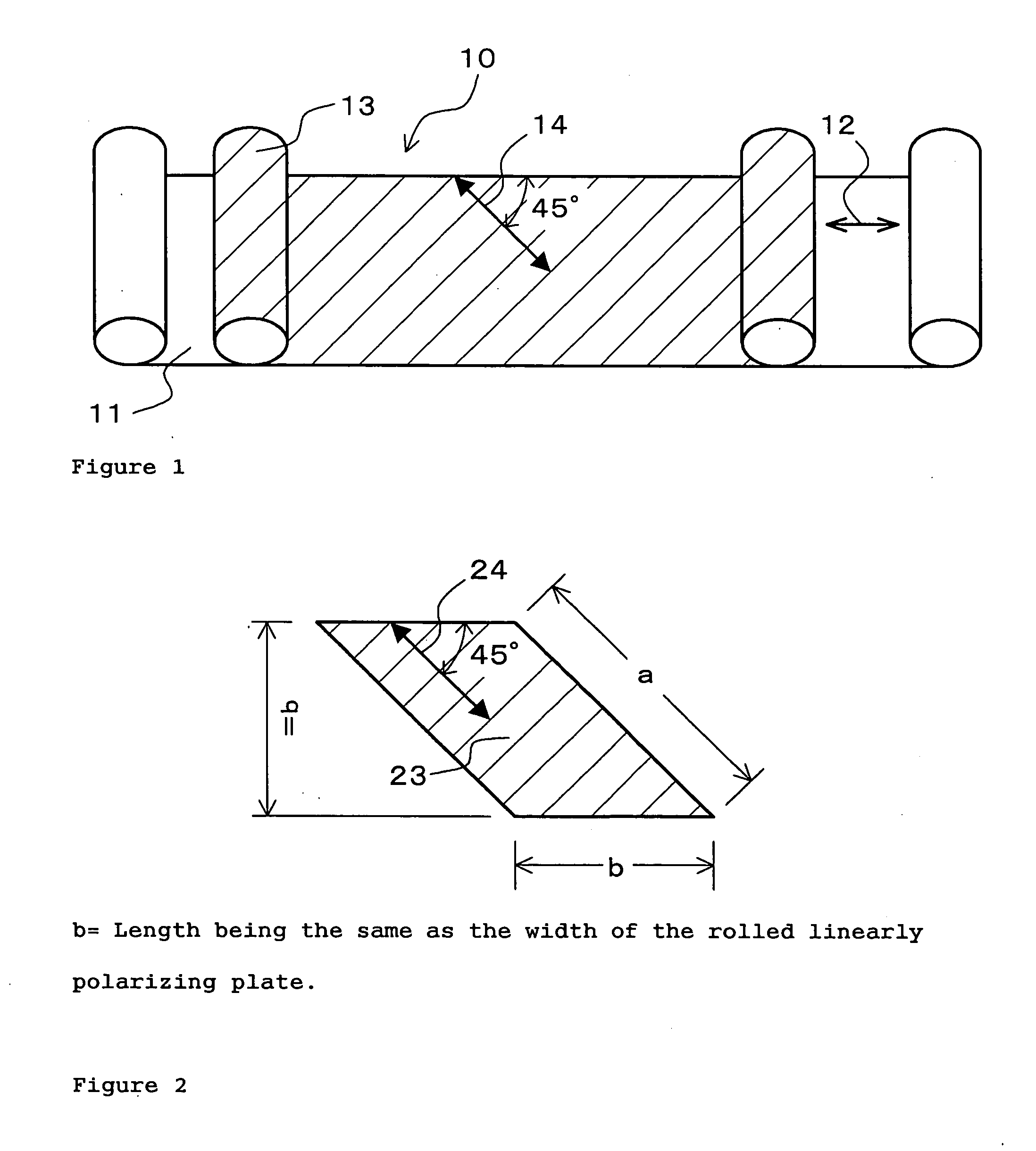
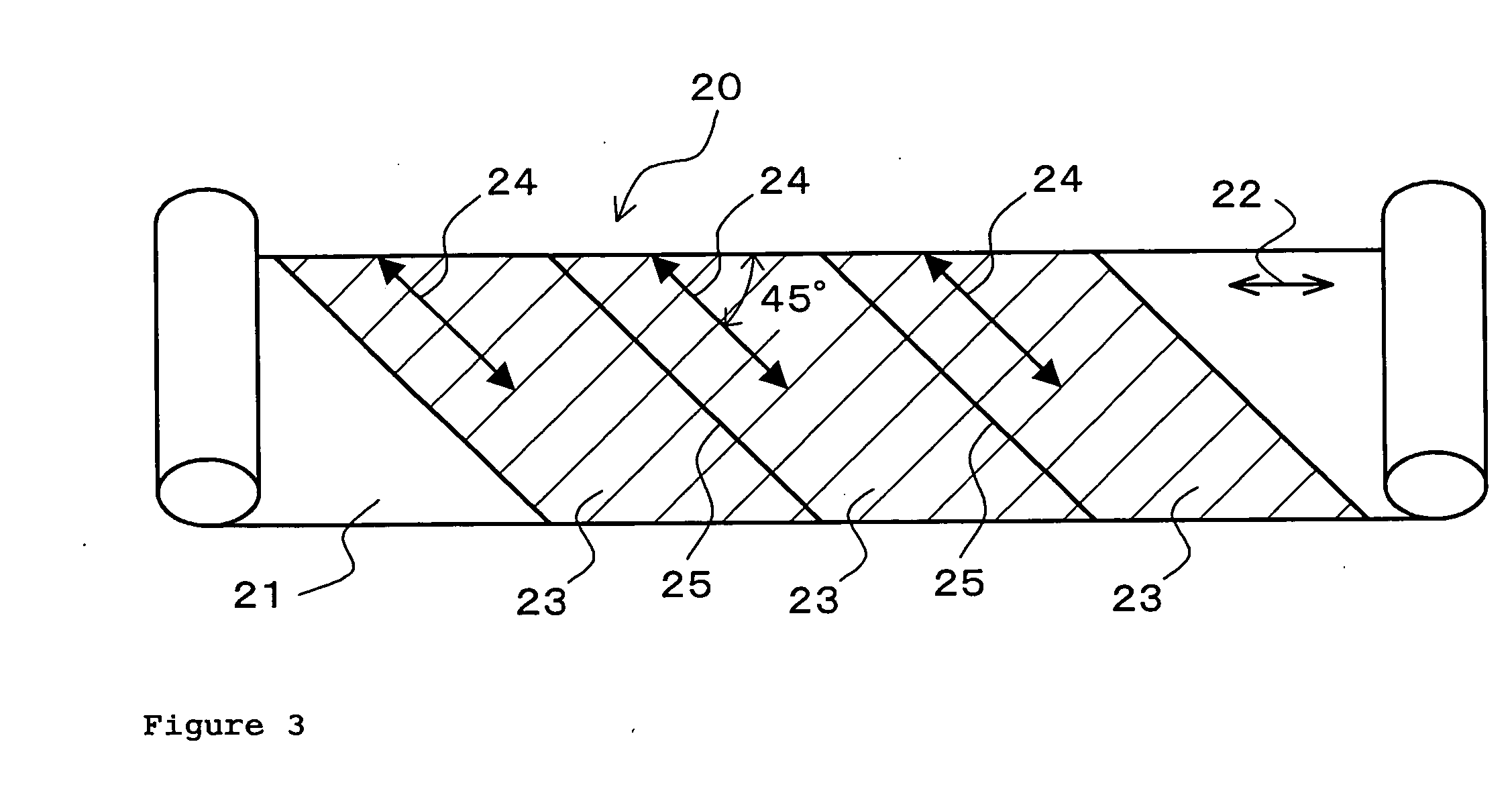
[0082] When sheet-like elliptically polarizing plates (length 100 mm×width 50 mm) were cut from the rolled elliptically polarizing plate (width 100 mm×length 5 m, the longitudinal direction and the absorption axis of the linear polarizing plate are laid in parallel) obtained in Example 1 in such a way that the length direction was laid in the absorption axis of the linear polarizing plate, 100 sheets of elliptically polarizing plates without joints were capable of being cut out. In this example, the taking out efficiency R calculated by Equation (1) above was 100%.

example 3

[0083] When sheet-like elliptically polarizing plates (length 50 mm×width 50 mm) were cut from the rolled elliptically polarizing plate (width 100 mm×length 5 m, the longitudinal direction and the absorption axis of the linear polarizing plate are laid in parallel) obtained in Example 1 in such a way that the length direction was laid in the absorption axis of the linear polarizing plate, 200 sheets of elliptically polarizing plates without joints were capable of being cut out. In this example as well, the taking out efficiency R calculated by Equation (1) above was 100%.


PUM

PropertyMeasurementUnit
wavelength regionaaaaaaaaaa
thicknessaaaaaaaaaa

Abstract

A rolled elliptically polarizing plate that is made by laminating a compensation film 13 having a coated layer made by a coating agent performing a compensation function on the surface of a rolled linear polarizing plate, the compensation film being a rolled film formed by application of a coating agent performing a compensation function to the surface of a transparent substrate, the linear polarizing plate and the compensation film being laminated by means of roll to roll processing by making the respective longitudinal directions approximately in parallel, or the above compensation film being formed by application of a coating agent performing a compensation function to the surface of the rolled linear polarizing plate.

Description

BACKGROUND OF THE INVENTION [0001] 1. Field of the Invention [0002] The present invention relates to an elliptically polarizing plate used for a display apparatus such as a liquid crystal display, organic electric light-emitting display, which is good in production efficiency and yield, and is suitable for reducing thickness of devices. And the present invention also relates to a method of producing the same. The invention further relates to a display apparatus such as a liquid crystal display, organic electric light-emitting display, touch panel, or the like, with using the elliptical polarizing plate. [0003] 2. Background of the Invention [0004] An elliptically polarizing plate used for a display apparatus such as a liquid crystal display is generally constructed by laminating a linear polarizing plate and a compensation film. In other words, a linear polarizing plate and a compensation film are laminated by means of an adhesive or the like so that the absorption axis the linear p...

Claims


Application Information

Patent Timeline
Patent Type & Authority Applications(United States)
IPC IPC(8): C09K19/00
CPCY10T428/1041G02B5/3016C09K2323/031G02B5/30
Inventor HAYASHI, HIDEKIMATSUOKA, YOSHIKI
Owner SUMITOMO CHEM CO LTD
Why Eureka
Try Eureka