
CVD apparatus for depositing polysilicon

a technology of polysilicon and cvd, which is applied in the direction of chemical vapor deposition coating, solid-state devices, coatings, etc., can solve the problems of glass substrate not being able to maintain its shape, complex processes, and taking a long time to perform processes, so as to prevent catalyst deterioration, reduce particle generation, and high quality

Inactive Publication Date: 2007-06-07
SAMSUNG MOBILE DISPLAY CO LTD +1
View PDF8 Cites 22 Cited by
  • Summary
  • Abstract
  • Description
  • Claims
  • Application Information

AI Technical Summary

Benefits of technology

[0040] Another aspect of the present embodiments is to provide a CVD apparatus in which catalyst deterioration is prevented, particle generation is minimized, and process parameter is not limited.
[0041] Still another aspect of the present embodiments is to provide a CVD apparatus for forming a high quality silicon thin film with low hydrogen content.

Problems solved by technology

However, a temperature of more than about 600° C. is required to form the polysilicon, and thus a glass substrate cannot maintain its shape at this temperature.
However, such conventional LTPS method has disadvantages in that the processes are complicated and much time is taken to perform the processes.
Further, the conventional LTPS method requires expensive equipment including a laser, thereby increasing production cost of the display device and lowering the competitiveness thereof.
However, these methods also require another processes in addition to the depositing process, so there are many problems in applying these methods to mass production.
Thus, the thin film formed by this method not only has bad crystallinity but also has increased hydrogen content.
The combination of Si—H in the thin film is easily separated by external energy, which deteriorates the reliability of the device.
In particular, this problem has a big effect on an organic light emitting diode (OLED), a field emission display (FED), a solar cell or the like, which uses the optical characteristic of material thereof.
However, such a conventional catalytic CVD apparatus using the catalyst has three problems: catalyst deterioration, particle generation, and a limited process parameter due to reaction between the catalyst and the reaction gas.
Further, the created tungsten silicide (WSi2) is harder than tungsten, and thus causes a thin film to be easily broken due to external impact, thereby decreasing the reliability of the system.
For example, the adhesion can be enhanced by heating the wall of the chamber at a temperature of more than 100° C., usually at a temperature of more than 300° C. However, in the conventional CVD apparatus, the wall of the chamber is in contact with the outside, so that it is impossible to heat the wall at such high temperature.
However, it is impossible to adjust the distance between the showerhead and the catalyst in such CVD apparatus, thereby limiting the characteristic improvement of the thin film.
However, this configuration is complicated to manufacture.
Further, to change the configuration of the catalyst, there is a problem of changing the showerhead.
Therefore, it is difficult to apply such limitation of the characteristic improvement to a large-sized display requiring a thin film that should have good characteristics and good thickness uniformity.

Method used


Image

  • CVD apparatus for depositing polysilicon
  • CVD apparatus for depositing polysilicon
  • CVD apparatus for depositing polysilicon

Examples


Embodiment Construction

[0056] Hereinafter, preferable embodiments will be described with reference to the accompanying drawings, wherein the preferred embodiments are provided to be readily understood by those skilled in the art.

[0057]FIG. 6 is a sectional view of a CVD apparatus according to an embodiment. The CVD apparatus according to an embodiment includes a chamber 30 in which to form a thin film on a substrate 38; a showerhead 32 placed in an upper part of the chamber 30 to inject reaction gas onto the substrate 38; a distributor 34 formed with distributing holes 34a to uniformly distribute the reaction gas; a catalyst hot wire unit 36 to heat the reaction gas injected through the distributing holes 34a of the distributor 34 and convert the reaction gas into ions or radicals; a chuck 39 on which the substrate 38 is mounted; and a discharging hole 31 to discharge the reaction gas, which has the same configuration as the conventional CVD apparatus.

[0058] Here, the CVD apparatus according to one embo...


PUM

PropertyMeasurementUnit
temperatureaaaaaaaaaa

Abstract

Disclosed is a CVD apparatus for depositing polysilicon without a separate following annealing process, the CVD apparatus comprising: a chamber to form a thin film on a substrate; a showerhead placed in an upper part of the chamber to inject reaction gas onto the substrate; a distributor formed with distributing holes to uniformly distribute the reaction gas; a catalyst hot wire unit to heat and dissolve the reaction gas injected through the distributing holes of the distributor; a chuck on which the substrate is mounted; a discharging hole to discharge the reaction gas; and a shielding wall provided as a lateral wall of the chamber and formed with a heater to suppress particle generation. With this configuration, the particle generation is minimized and thus the yield is enhanced. Also, the thin film has good crystallinity, and decreased hydrogen content.

Description

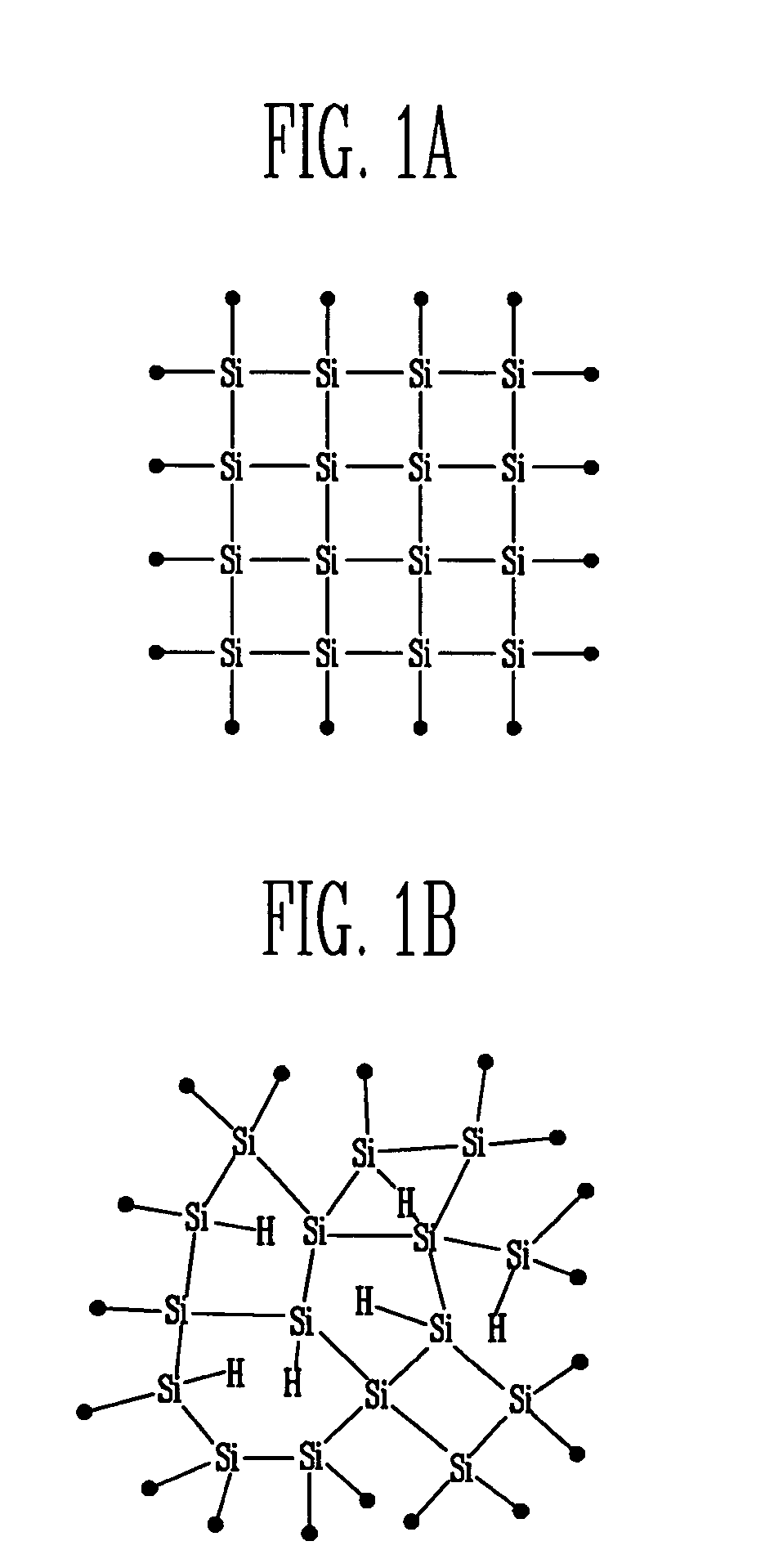
CROSS-REFERENCE TO RELATED APPLICATIONS [0001] This application claims the benefit of Korean Patent Application No. 10-2005-0039926, filed on May 12, 2005, in the Korean Intellectual Property Office, the disclosure of which is incorporated herein by reference. BACKGROUND OF THE INVENTION [0002] 1. Field of the Invention [0003] The present embodiments relate to a chemical vapor deposition (CVD) apparatus for depositing polysilicon, and more particularly, to a CVD apparatus for depositing polysilicon without a separate following annealing process. [0004] 2. Description of the Related Art [0005] In general, when silicon (Si) is deposited on a glass substrate, silicon is either formed as polysilicon (P-Si) or amorphous silicon (A-Si). [0006]FIGS. 1A and 1B show structures of polysilicon and amorphous silicon, respectively. Silicon is generally formed as polysilicon at a temperature of more than about 600° C. or as amorphous silicon at a temperature of less than about 600° C. [0007] In c...

Claims


Application Information

Patent Timeline
Patent Type & Authority Applications(United States)
IPC IPC(8): H01L21/84H01L21/44C23C16/00
CPCC23C16/24C23C16/44H01L27/13H01L29/6675
Inventor KIM, MYOUNG SOOKIM, HAN KIJEONG, SEOK HEON
Owner SAMSUNG MOBILE DISPLAY CO LTD
Learn More