Intake device of internal combustion engine

a technology of internal combustion engine and intake device, which is applied in the direction of combustion-air/fuel-air treatment, intake silencer combination, air cleaner and silencer combination, etc. it can solve the problems of reducing the sound pressure level, and reducing the sound pressure of air intake sound. , to achieve the effect of effectively lowering the sound pressure of air intake sound, improving the tone of air intake sound

Active Publication Date: 2007-06-14
MAHLE JAPAN LTD
View PDF4 Cites 39 Cited by
  • Summary
  • Abstract
  • Description
  • Claims
  • Application Information

AI Technical Summary

Benefits of technology

[0014] An intake device of an internal combustion engine as claimed in claim 6 comprises an intake air passage through which intake air is introduced into the internal combustion engine, and a resonance passage branched off from the intake air passage, wherein the resonance passage has one end opened to atmospheric air and the other end connected to the intake air passage, the resonance passage having a passage length set to add a sound pressure in a certain frequency range to air intake sound. With this, a part of air intake sound is introduced from the intake air passage to the resonance passage. In other word, a part of air intake sound is allowed to leak from the intake air passage to the resonance passage thereby lowering the sound pressure of air intake sound. Additionally, air intake sound introduced into the resonance passage is resonated within the resonance passage, thereby making it possible to release the sound pressure having a frequency component required for improving the tone of air intake sound, from one end of the resonance passage.
[0015] The invention of claim 7 is, in the intake device as claimed in claim 6, that a sound-transmissible material having a gas permeability is disposed in the resonance passage. With this, a part of air intake sound is introduced from the intake air passage through the sound-transmissible material, thereby further effectively lowering the sound pressure of air intake sound.
[0016] The invention of claim 8 is, in the intake device of an internal combustion engine as claimed in claim 6, that an air cleaner is disposed in the intake air passage, the resonance passage being communicated with the intake air passage at an upstream side of the air cleaner, wherein a change-over valve is disposed in the intake air passage at a connecting section to which the resonance passage is connected, the change-over valve being adapted to close either one of the resonance passage and an upstream side section of the intake air passage relative to the connecting section and open the other in accordance with an engine operating condition, wherein the change-over valve whose at least a part is formed of a sound-transmissible material having a gas permeability. With this, according to the engine operating condition, an air intake sound reduction and a local resonance in an intake air introduction path at the upstream side of the air cleaner can be achieved during a low engine speed operation of the engine, and a sufficient air flow amount to the engine through a first outside air duct can be secured while a sound pressure having a frequency component effective for improving the tone of air intake sound is released from a second outside air duct during medium and high engine speed operation of the engine.

Problems solved by technology

Accordingly, the sound pressure characteristics of this tuned air intake sound does not necessarily change linearly with an increase in engine speed, so that there is a fear of providing uncomfortable feeling to a driver.
However, in the arrangement of the patent literature 1, it is necessary to tune the length of the intake air duct, the passage cross-sectional areas inside the intake air ducts and the like in order to generate desired air intake sound during the engine high load operation, and therefore there is a fear that a layout of the intake system is largely restricted.
However, in this patent literature 2, there is such a problem that the sound pressure level become rather too low at a part of frequency ranges because of being arranged from such a viewpoint that the sound pressure level is sufficient to meet a certain target level only on the basis of taking preference of silence of the intake system, so that the tone feeling of air intake sound felt by the driver within the passenger compartment becomes unsatisfactory to the driver.

Method used


Image

  • Intake device of internal combustion engine
  • Intake device of internal combustion engine
  • Intake device of internal combustion engine

Examples


first embodiment

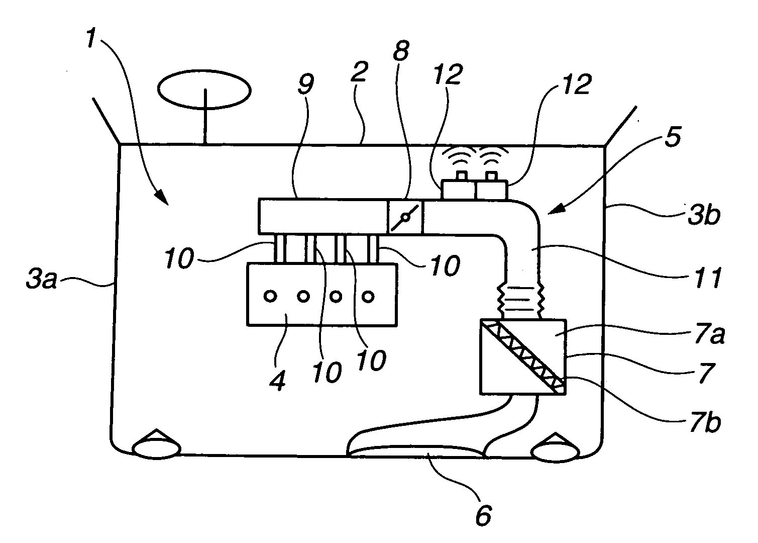
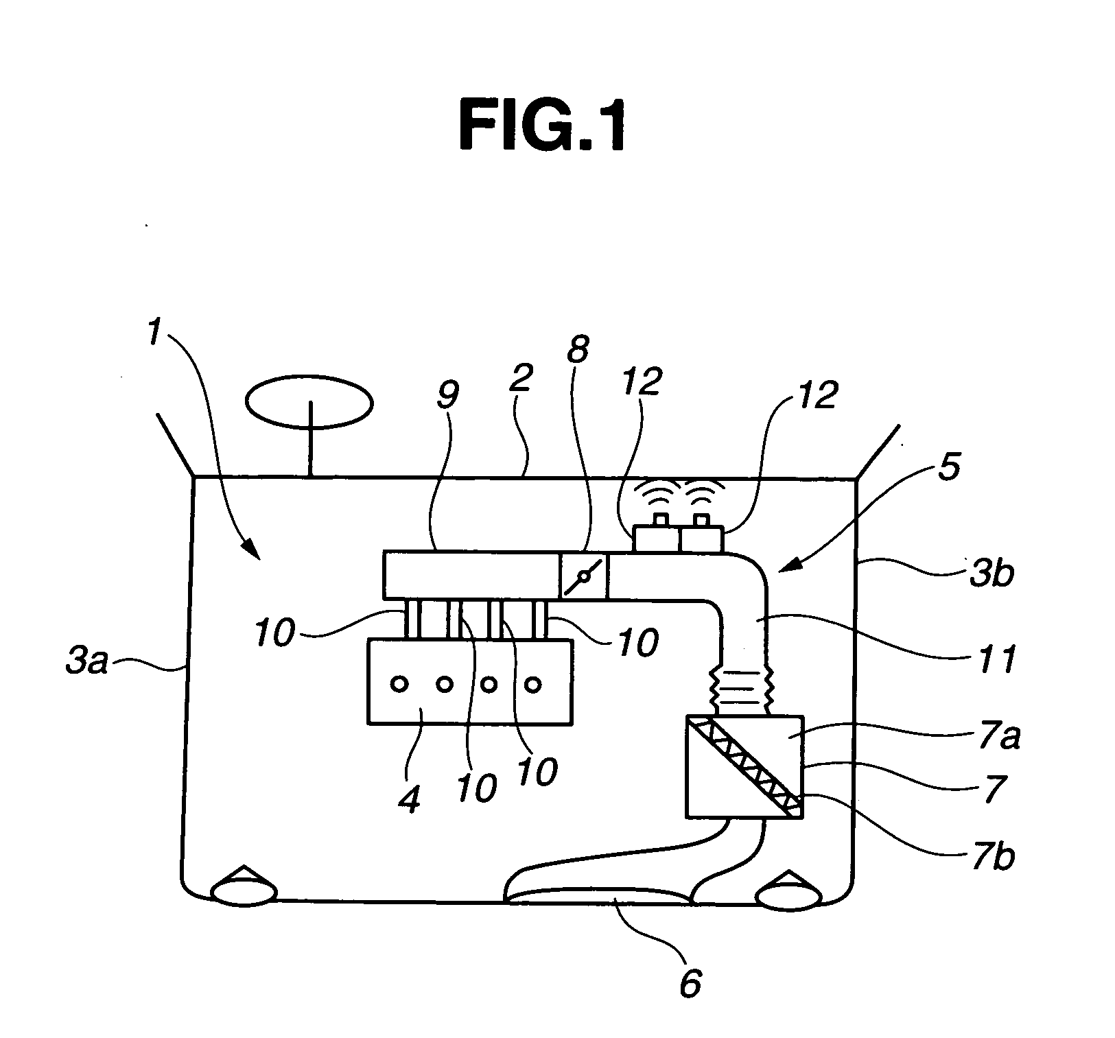
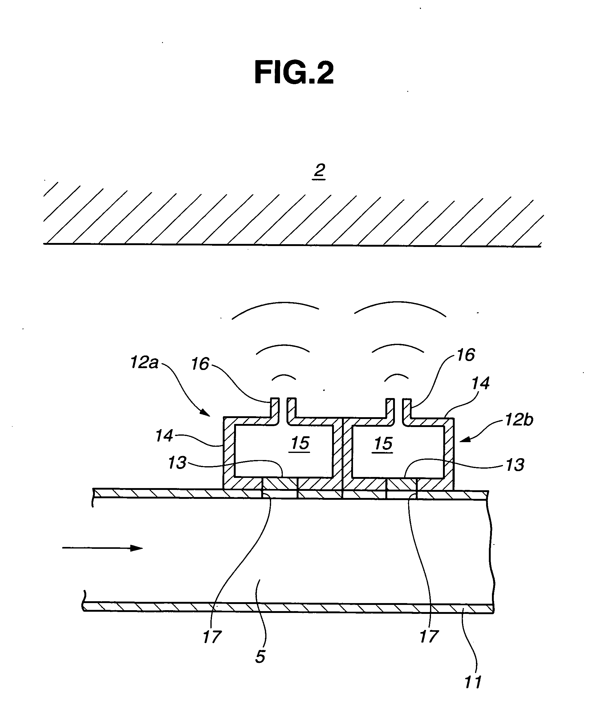
[0057] Structure of the resonator 12 will be discussed. In this first embodiment, a structure in which the neck section 16 is narrowed as compared with the volume chamber 14 so as to obtain a so-called cavity resonance (Helmholtz resonance) in accordance with vibrations of the resonating body 13. The neck section 16 of the resonator 12 is located near the dash panel 2 defining the engine compartment 1 and disposed such that its opening faces the dash panel 2.

[0058] In this first embodiment, the sound pressure released from each resonator 12a, 12b is set within a certain frequency range in order to obtain such a sound pressure characteristics of air intake sound that the sound pressure changes generally linearly with an increase in engine speed by adding the sound pressure released from each resonator 12a, 12b to the air intake sound generated from the air intake system 5. In other words, each resonator 12a, 12b is set so as to obtain such a sound pressure characteristics of air inta...

third embodiment

[0076] Next, the present invention will be discussed. As shown in FIG. 15, a V-type six-cylinder engine 73 is disposed within an engine compartment 72 defined by a dash panel 70 and left and right side panels 71a, 71b, and the like. An intake system 74 through which intake air is introduced is connected to the engine 73. The intake system 74 is disposed in such a manner that an intake air taking-in opening 75 is opened to the front surface of a vehicle. Air taken in through the intake air taking-in opening 75 is introduced through an air cleaner 76 and a throttle valve 77 into an intake air collector 78, and thereafter is supplied to the combustion chambers of respective cylinders through respective branch pipes 79 from the intake air collector 78. A clean side duct 80 for connecting the clean side 76a of the air cleaner 76 and the throttle valve 77 is provided with two resonators 81a, 81b which respectively release certain sound pressures which are similar to each other under the a...

fourth embodiment

[0091] With reference to FIGS. 22 to 24, explanation will be made on the first outside air duct 106 and the second outside air duct 109 serving as an essential part of the intake device 105 in the

[0092] The first outside air duct 106 is formed generally rectangular in passage sectional shape, at a connecting section 115 on the side of the one end 106a to which the second outside air duct 109 is connected.

[0093] The passage sectional area of the first outside air duct 106 is set larger than the passage sectional area of the second outside air duct 109. Additionally, in the first outside air duct 106, the passage length between the one end 106a and the connection section 115 of the first outside air duct 106 is set short as compared with that of the second outside air duct 109.

[0094] The second outside air duct 109 branched off from the first outside air duct 106 is so set in axial length or duct length as to release from its one end 109a sound having a frequency component required ...


PUM


Abstract

A resonator 13 is provided including a resonating body 13 which is vibrated by intake air pulsation in an intake system 5, a volume chamber 14 connected through the resonating body 13 to the intake system 5, and a neck section 16 through which an interior space 15 of the volume chamber 14 is communicated with outside. The interior space 15 of the volume chamber 14 and interior of the intake system 5 are partitioned by the resonating body 13. The resonator is so set that a sound pressure in a certain frequency range is released from the neck section 16 to the outside under vibration of the resonating body 13. With this, the sound pressure characteristics of air intake sound can follow a rise in engine speed.

Description

TECHNICAL FIELD [0001] This invention relates to an intake device of an internal combustion engine. BACKGROUND ART [0002] It is well known as a conventional technique, in an intake system of an internal combustion engine, to reduce intake air pulsation caused by reciprocating movement of a piston and an intake valve by regulating the diameter and length of an intake passage such as an intake duct or the like, the volume of an air cleaner constituting a part of the intake system and by adding a resonator to the intake system. [0003] However, in such a known technique, tuning air intake sound within a preset certain target sound pressure characteristics range is the main object. Accordingly, the sound pressure characteristics of this tuned air intake sound does not necessarily change linearly with an increase in engine speed, so that there is a fear of providing uncomfortable feeling to a driver. [0004] A patent literature 1 discloses obtaining air intake sound having powerful feeling...

Claims


Application Information

Patent Timeline
Patent Type & Authority Applications(United States)
IPC IPC(8): F02M35/10F02B27/00F02M35/04F02M35/12F02M35/14
CPCF02M35/04F02M35/14Y02T10/146F02M35/1238F02M35/1266F02M35/1272F02M35/1294F02B27/008F02M35/161Y02T10/12
Inventor SHINADA, MASASHISAITO, YUTA
Owner MAHLE JAPAN LTD
Why Eureka
Try Eureka