
High frequency driven high pressure micro discharge

a high-pressure, micro-discharge technology, applied in gas-filled discharge tubes, gaseous cathodes, solid cathodes, etc., can solve the problems of insufficient electric field to substantially ionize gas, high brightness of light sources with such short wavelengths, and insufficient light output power and light intensity limits, etc., to achieve the effect of increasing heat transfer and reducing the intensity of processes

Inactive Publication Date: 2007-06-14
RUTGERS THE STATE UNIV
View PDF7 Cites 7 Cited by
  • Summary
  • Abstract
  • Description
  • Claims
  • Application Information

AI Technical Summary

Benefits of technology

[0009] One aspect of the present invention provides a method of producing vacuum ultraviolet light. The method according to this aspect of the invention desirably includes the steps of maintaining a gas mixture containing a halogen capable of forming excimer-like excited halogen molecules of the form Z2* where Z represents the halogen, or a gas mixture containing a rare gas and a halogen capable of forming excimers of the form RGZ*, where RG represents the rare gas, in a chamber so that at least a portion of the gas mixture is disposed in an emission region between a pair of electrodes at a selected pressure, applying electrical potential between the electrodes to form an electrical discharge in the emission region and apply power to the gases in the emission region at a selected power density, and maintaining a concentration of the halogen in the emission region substantially equal to an optimum concentration. Preferably, the pressure in the chamber is at least about 0.3 bar, and more preferably 0.3 bar to 1.5 bar. The power density in the emission region to generate a bright light source based on Z2* and RG2* excimer radiation desirably is at least about 20 kW / cm3. Under typical conditions, the optimum molar concentration of the halogen is between about 1% and about 5% of the total gas mixture, more preferably the halogen concentration is about 2%. Maintaining the concentration of the halogen substantially equal to the optimum concentration of halogen will maximize ultraviolet emission from excimers of the form RGZ* or Z2* at the selected pressure and power density. The method may further comprise the step of passing the gas mixture through the chamber at a selected flow rate. With this further step, the concentration of the halogen in the gas passed through the chamber is substantially equal to an optimum concentration, which maximizes the ultraviolet emissions at the selected flow rate, pressure and power density.

Problems solved by technology

In addition, such microimaging of features requires high brightness of light sources with such short wavelengths.
However, such electron beam approaches typically require creation of an electron beam in a chamber separate from the chamber containing the gases, and introduction of the electron beam through a beam window.
The electron beam window apparatus typically imposes some limits on the electron beam power which may be applied to the gases, which in turn imposes limits on the light output power and light intensity.
Thus, the electrical power is applied under conditions such that within a part of the space between the electrodes, the electric field is insufficient to substantially ionize the gas.
While this approach provides a useful light source, the applied power and hence the light emission are limited by the need to limit the field.

Method used


Image

  • High frequency driven high pressure micro discharge
  • High frequency driven high pressure micro discharge
  • High frequency driven high pressure micro discharge

Examples


example 1

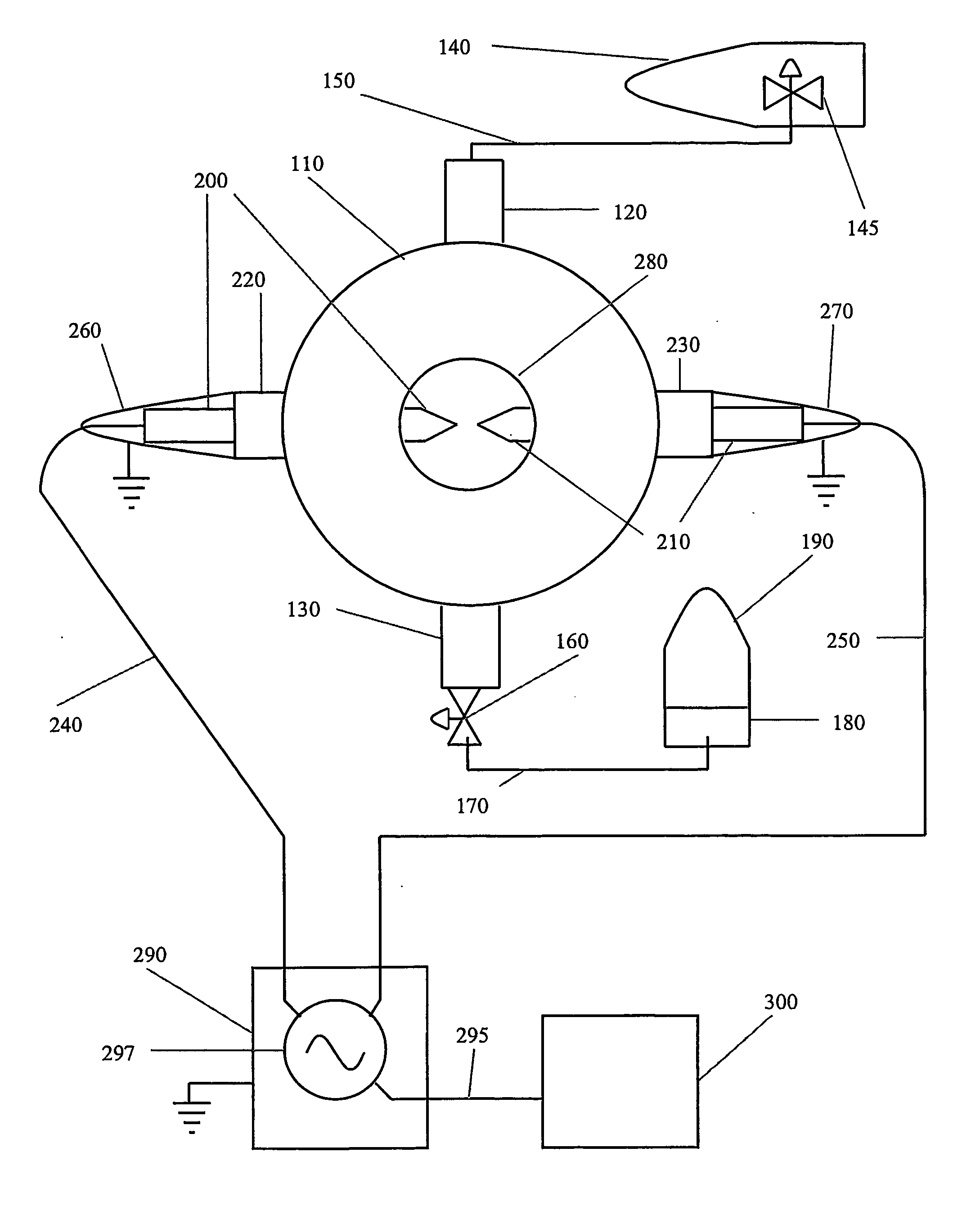
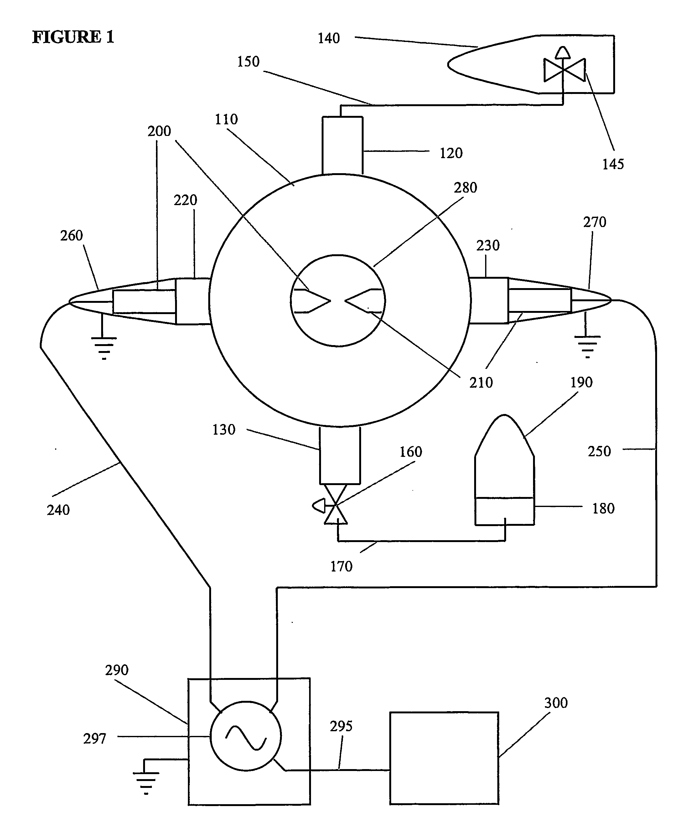
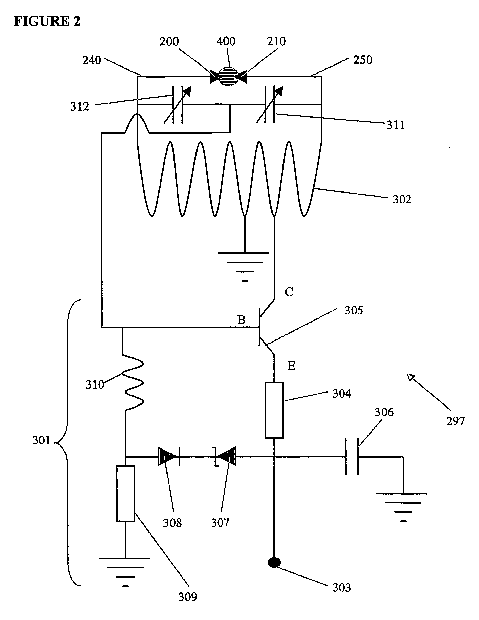
[0059] 68% He, 30% Ar, and 2% F2 at 500 mbar total pressure was used to form the ArF* excimer and produce 193 nm light, with brass needle tip electrodes as shown in FIG. 3. The gas flow through the chamber was less than 60 sccm flow of the gas. The voltage was set at 24 volts at the power supply, supplying −24 volts to the oscillator circuit. FIG. 6 shows the intensity of the output from the apparatus vs. the wavelength output from the apparatus, and FIG. 7 shows the light power output of the apparatus over a period of time. Similar results were obtained using less rounded brass electrodes at about 1 bar total pressure and at 30 volts at the power supply.

example 2

[0060] Pure Xe of research grade at 800 mbar total pressure was used to form the Xe2* excimer and produce 172 nm light. There was no gas flow. The voltage was set at 32 volts at the power supply, supplying −32 volts to the oscillator circuit. Electrodes having spheroidal ends as illustrated in FIG. 5 were used, with the spheroidal ends being about 1 mm in diameter. The electrodes were made of stainless steel and, they were separated by about 0.5 mm to about 1 mm. FIG. 8 shows the intensity of the output from the apparatus vs. the wavelength output from the apparatus, and FIG. 9 shows the power output of the apparatus over a period of time.

example 3

[0061] Pure Kr of research grade with a total pressure between about 300 mbar and 1 bar was used to form the Kr2* excimer and produce 145 nm light. There was no gas flow. The voltage was set at 32 volts at the power supply. Electrodes having spheroidal ends (FIG. 5) were used, with the spheroidal end being about 1 mm in diameter. The electrodes were made of stainless steel and, they were separated by about 0.5 mm to about 1 mm. FIG. 10 shows the intensity of the output of the apparatus vs. the wavelength output from the apparatus.


PUM


Abstract

A method and apparatus are provided for generating light such as ultraviolet light from excimer-forming gases. Gases are excited by radio frequency alternating current powered electrodes (200, 210) to form excimers that will decay and emit vacuum ultraviolet light. The halogen concentration is optimized so as to optimize emissions from halogen excimers (Z2*) or mixed rare gas / halogen excimers (RGZ*). Emissions from rare gas excimers (RG2*) are maximized by maintaining the gas in the discharge region at a relatively low temperature, desirably below 700° K, so that the average kinetic energy of gas particles is less than the vibrational excitation energy of the excimer and substantially less than the dissociation energy of the excimer. Relatively large electrodes (202, 204) can be used to cool the plasma.

Description

CROSS REFERENCE TO RELATED APPLICATION [0001] This application claims the benefit of U.S. Provisional Application 60 / 492,669, filed Aug. 5, 2003, the disclosure of which is fully incorporated herein by reference.TECHNICAL FIELD [0002] The present invention relates to methods and apparatus for generating light such as ultraviolet light from excimer-forming gases. BACKGROUND ART [0003] There has been a need for improved light sources capable of generating ultraviolet light in the spectral region of between about 200 and 400 nanometers wavelength, commonly referred to as the “ultraviolet” or “UV” region and, between about 100 and 200 nanometers wavelength, commonly referred to as the “vacuum ultraviolet” or “VUV” region. VUV light is absorbed by almost all substances, including water and air, and therefore, can only be transmitted in a vacuum. VUV photons have energies on the order of 10 electron volts (10 eV) and are capable of breaking chemical bonds of many compounds. Thus VUV light...

Claims


Application Information

Patent Timeline
IPC IPC(8): H01J17/36H01J11/04H05B41/00H05B37/00H01S
CPCH01J61/0732H01J61/16H01J61/28H01J61/86H05B41/24
Inventor SALVEMOSER, MANFREDMURNICK, DANIEL E.
Owner RUTGERS THE STATE UNIV
Learn More