Bed apparatus and MRI apparatus

a bed and magnetic resonance imaging technology, applied in the direction of applications, diagnostic recording/measuring, bearing unit rigid support, etc., can solve the problems of troublesome moving operation, increased size of the bed apparatus, and inability to set the table-top by a long distance, so as to prevent an increase in length and prevent an increase in the size of the apparatus

Inactive Publication Date: 2007-06-28
KK TOSHIBA +1
View PDF7 Cites 41 Cited by
  • Summary
  • Abstract
  • Description
  • Claims
  • Application Information

AI Technical Summary

Benefits of technology

[0018] Therefore, according to the present invention to provide the bed apparatus and MRI apparatus, while the intermediate unit with a simple structure moves in the longitudinal direction, the table-top can be moved in the same direction as the intermediate unit. Accordingly, it is possible to prevent an increase in length in the longitudinal direction of the table-top, and thus to prevent an increase in size of the apparatus because the table-top is set at a position more apart from the bed supporting unit than the intermediate unit is.

Problems solved by technology

In the bed apparatus including the mechanical unit for moving the table-top, however, it is impossible to set the table-top by moving the table-top by a distance longer than the distance of the table-top excluding a portion thereof attached with the mechanical unit.
As a result, there arises a problem of an increase in size of the bed apparatus.
Thus, the apparatus has a problem in that the moving operation is troublesome.
As a result, there arises a problem of complication in configuration of the apparatus.
In this case, there arises a problem of an increase in size of a whole body (WB) coil for transmission.
Further, electrical wiring and the like cannot be located below the table-top at the center position in the width direction of the table-top also in such diagnostic imaging apparatuses as the X-ray CT apparatus and the PET apparatus.

Method used


Image

  • Bed apparatus and MRI apparatus
  • Bed apparatus and MRI apparatus
  • Bed apparatus and MRI apparatus

Examples


first embodiment

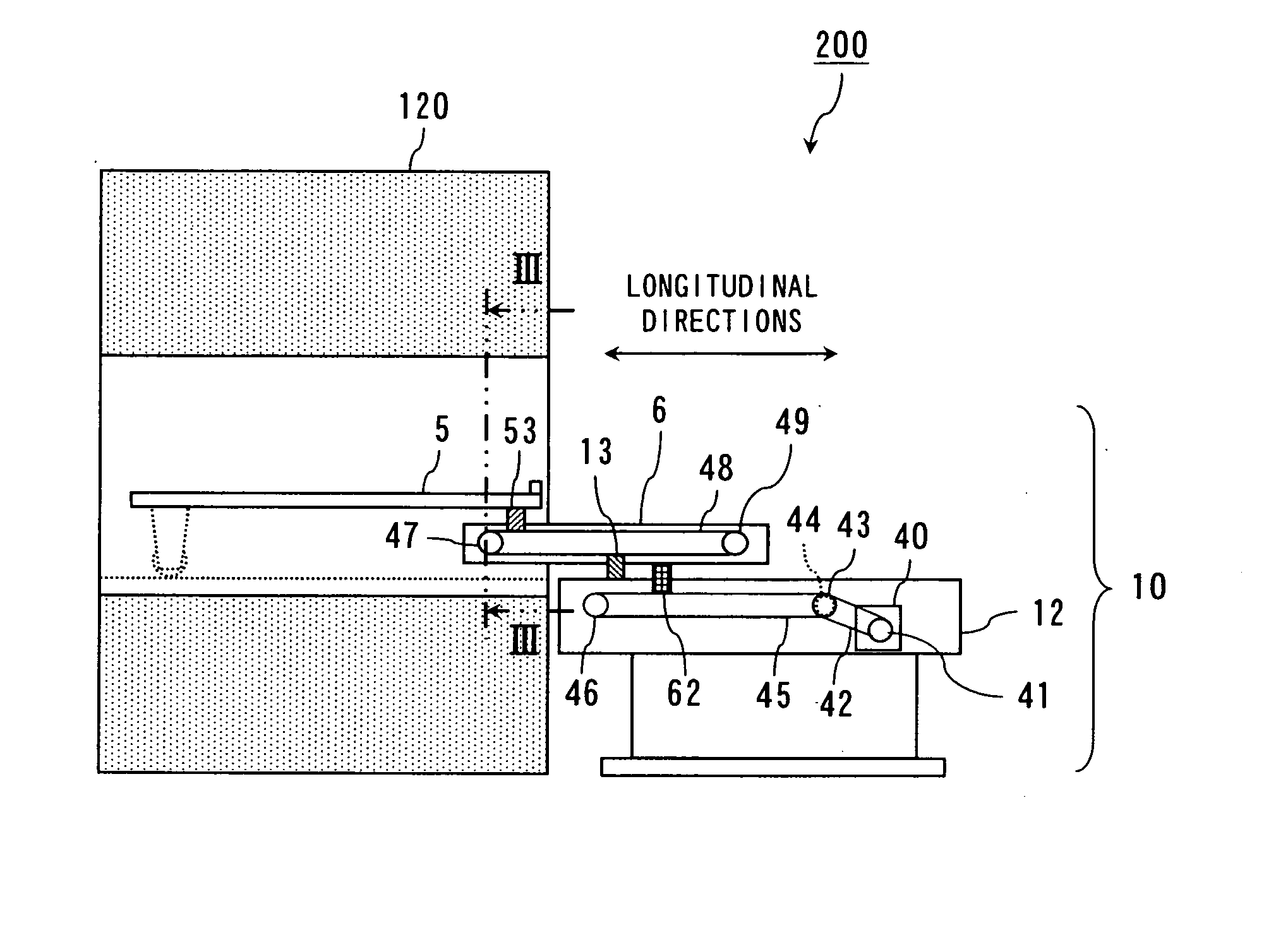
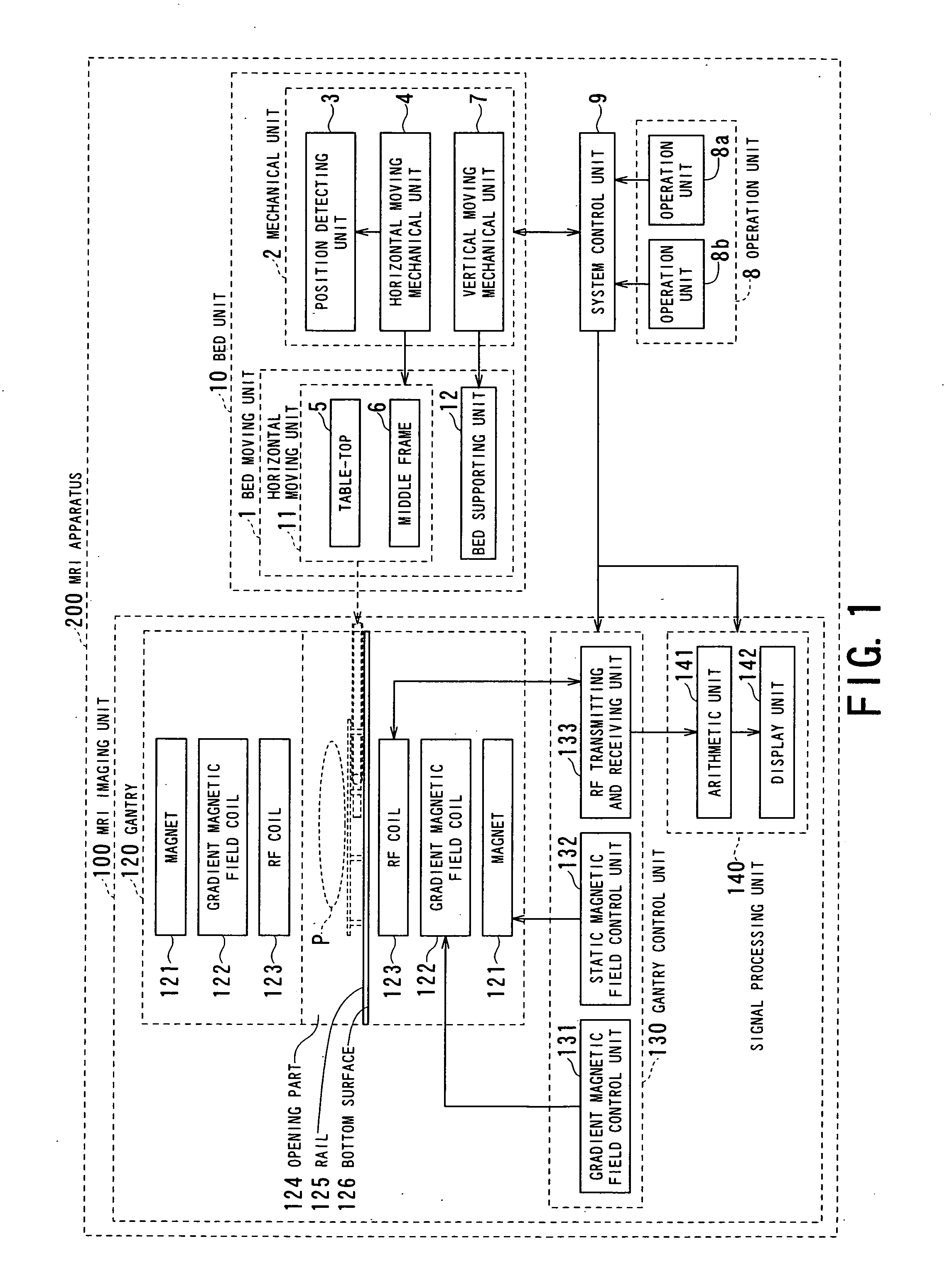
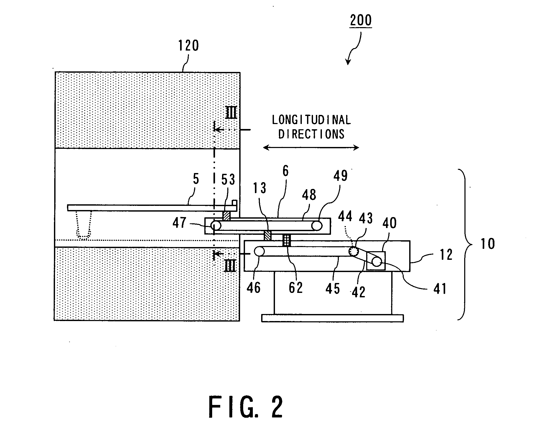
[0056] Description will be made below on a first embodiment of an MRI apparatus according to the present invention with reference to FIGS. 1 to 23. FIG. 1 is a block diagram illustrating a configuration of the MRI apparatus (a bed apparatus) according to the first embodiment of the present invention.

[0057]FIG. 1 illustrates an MRI apparatus 200 according to the first embodiment of the present invention. The MRI apparatus 200 has an MRI imaging unit 100 for performing MRI imaging of a object P, a bed unit 10 for setting the object P at an imaging position in the MRI imaging unit 100, an operation unit 8 for operating the MRI imaging unit 100 and the bed unit 10, and a system control unit 9 for controlling the MRI imaging unit 100 and the bed unit 10 on the basis of a signal sent by the operation unit 8.

[0058] The MRI imaging unit 100 has a gantry 120 for generating a magnetic field around the object P, a gantry control unit 130 for controlling the magnetic field inside the gantry 1...

second embodiment

[0144] Description will be made below on a second embodiment of the bed unit of the MRI apparatus according to the present invention with reference to FIGS. 24 to 35. FIG. 24 is a block diagram illustrating a configuration of an MRI apparatus a bed apparatus) according to the second embodiment of the present invention.

[0145]FIG. 24 illustrates an MRI apparatus 200A according to the second embodiment of the present invention. The MRI apparatus 200A illustrated in FIG. 24 is different from the MRI apparatus 200 illustrated in FIG. 1 in that a bed moving unit 1a of a bet unit (i.e., a bed apparatus) 10a illustrated in FIG. 24 is provided with two middle frames 6a and 6b, and that a horizontal moving mechanical unit 4a enables the bed moving unit 1a to horizontally move in the longitudinal direction. Components of the same configuration as the components of the first embodiment are designated with the same reference numerals, and description thereof will be omitted. Further, FIGS. 3 to...


PUM


Abstract

A bed apparatus has a table-top movable at least in a longitudinal direction, a bed supporting unit located below the table-top, an intermediate unit located at a position between the table-top and the bed supporting unit and not overlapping with a center in a width direction of the table-top, and movable in the same direction as the table-top, and a changing unit configured to change a relative positional relationship of the table-top and the intermediate unit while the intermediate unit moves with respect to the bed supporting unit.

Description

BACKGROUND OF THE INVENTION [0001] 1. Field of the Invention [0002] The present invention relates to a bed apparatus and a magnetic resonance imaging (MRI) apparatus for use in a diagnostic imaging apparatus. [0003] 2. Description of the Related Art [0004] A diagnostic imaging apparatus for performing diagnostic imaging by imaging an object includes an MRI apparatus, an X-ray computed tomography (CT) apparatus, a positron emission tomography (PET) apparatus, an X-ray diagnostic apparatus, and the like. [0005] The diagnostic imaging apparatus, such as the MRI apparatus, the X-ray CT apparatus, the PET apparatus, and the like, includes a stage unit formed with an opening for performing the imaging. The imaging is performed with the object inserted in the opening part. Further, an X-ray diagnostic apparatus for the circulatory system includes an imaging unit provided with an X-ray generation unit and an X-ray detection unit, which are held at a C-shaped end portion thereof to face each...

Claims


Application Information

Patent Timeline
Patent Type & Authority Applications(United States)
IPC IPC(8): A61G13/06A61G13/00
CPCA61B5/0555A61B5/055
Inventor HIYAMA, YOICHI
Owner KK TOSHIBA
Why Eureka
Try Eureka