Active radio frequency coil for high field magnetic resonance imaging

a radio frequency coil and high field technology, applied in the direction of dynamo-electric relays, using reradiation, instruments, etc., can solve the problems of reducing the efficiency of conventional passive radio frequency coils, and reducing the effect of arrangement negative resistan

Inactive Publication Date: 2007-06-28
NEW YORK UNIV
View PDF26 Cites 8 Cited by
  • Summary
  • Abstract
  • Description
  • Claims
  • Application Information

AI Technical Summary

Benefits of technology

[0009] In a further exemplary embodiment of the present invention, a varactor may be provided which is capable of controlling the negative resistance of the arrangement.

Problems solved by technology

Such higher resonance frequency can result in a more significant coil loss that otherwise could be neglected in a low field (e.g., 1.5 T or below).
This coil loss may includes a radiation loss and a conductor loss.
Thus, the efficiency of conventional passive radio frequency (“RF”) coils is reduced, likely significantly, when the resonance frequency increases.
Such reduction in efficiency of the conventional passive RF coils may compromise the higher SNR that is obtained by increasing the static magnetic field.
However, the use of the active devices not been significantly utilized in the conventional MRI coil designs.

Method used


Image

  • Active radio frequency coil for high field magnetic resonance imaging
  • Active radio frequency coil for high field magnetic resonance imaging
  • Active radio frequency coil for high field magnetic resonance imaging

Examples


Embodiment Construction

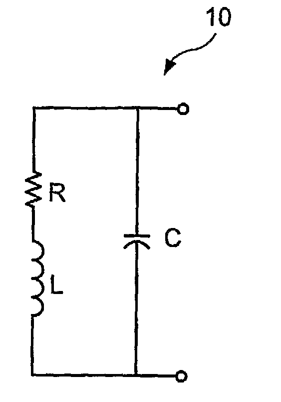
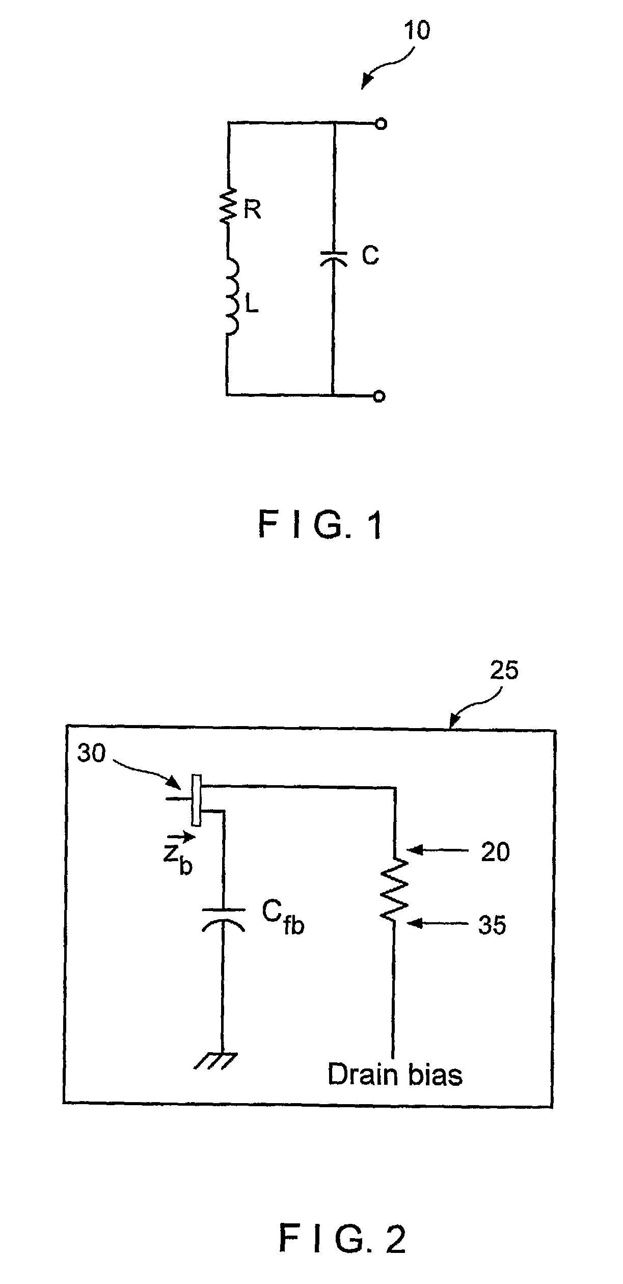
[0019] Conventional MRI RF coils have utilized passive resonators (“PR”) which can be modeled with a variety of LCR circuits, as described in Chen C-N et al., Biomedical Magnetic Resonance Technology, Adam Hilger (1989). Although there are some active parts on various coils, such as diodes, these active parts are likely only provided for a transmit / receive (“TR”) switch, and generally do not contribute to coil tuning and matching. To demonstrate the limitation of passive resonators in lossy conditions which is likely the reality in high field, it is possible to analyze a simplified circuit model for a conventional surface coil 10 (shown in FIG. 1) In this conventional coil 10, L is the inductance of copper strip, C is the tuning capacitor, and a resistor R is the sum of sample loss and coil loss. As shown in FIG. 1, the resistor R and the inductor L are provided in series, and such arrangement of the resistor R and the inductor L is provided in parallel with the capacitor C. The res...


PUM


Abstract

As the static magnetic field used in Magnetic Resonance Imaging (“MRI”) instruments increases the resonance frequency also increases. Consequently, the signal lost due to the coil becomes an issue. To compensate for this loss, it is possible to use an active device, such as a diode, a transistor, etc., with the radio frequency coil, MRI arrangement and method according to exemplary embodiments of the present invention to generate negative resistance to cancel the coil loss resistance. In this manner, the efficiency of the RF coil at high frequency can be improved.

Description

CROSS-REFERENCE TO RELATED APPLICATION [0001] The present application claims priority from U.S. Patent Application No. 60 / 551,145, filed Mar. 8, 2004, the entire disclosure of which is incorporated herein by reference.BACKGROUND OF THE INVENTION [0002] Using a magnetic resonance imaging (“MRI”) system, a substantially uniform main magnetic field is usually generated within an examination region. The main magnetic field polarizes the nuclear spin system of a subject (or a portion thereof) being imaged within the examination region. Magnetic resonance is excited in dipoles which align with the main magnetic field by transmitting radio frequency excitation signals into the examination region. Conventionally, radio frequency pulses that are transmitted via a radio frequency (“RF”) coil assembly move the dipoles out of alignment with the main magnetic field, and cause a macroscopic magnetic moment vector to precess around an axis parallel to the main magnetic field. Then, a corresponding...

Claims


Application Information

Patent Timeline
Patent Type & Authority Applications(United States)
IPC IPC(8): H01H53/00G01V3/00G01R33/36
CPCG01R33/3415G01R33/3453G01R33/36G01R33/3621
Inventor LEE, RAY F.
Owner NEW YORK UNIV
Why Eureka
Try Eureka