
Power generation system

a power generation system and power generation technology, applied in the direction of hydro energy generation, motors, electric generator control, etc., can solve the problems of alarming increasing rate, numerous harmful pollution to the natural environment, non-renewable materials, etc., and achieve the effect of convenient erecting, easy erecting and maintaining

Inactive Publication Date: 2007-07-05
CHIU YU
View PDF7 Cites 24 Cited by
  • Summary
  • Abstract
  • Description
  • Claims
  • Application Information

AI Technical Summary

Benefits of technology

[0006] It is another object of the present invention to provide an electrical power generation system may be easily erected at any location.
[0007] It is another object of the present invention to provide an electrical power generation system which is easy to erect and maintain.
[0008] It is another object of the present invention to provide an electrical power generation system which does not pose any harmful effect to the natural environment.

Problems solved by technology

Fossil fuel such as coal is a non-renewable material which is depleting in an ever alarming increasing rate that it will soon become unavailable.
Also, the burning of fossil fuel in the production of electrical power also produces numerous harmful pollution to the natural environment.
On the other hand, nuclear power generation poses potential wide spread natural disasters in case of system accident or failure such as a melt down.
The harmful effect from such disasters may last for a long time.
Furthermore, the disposal of the spent nuclear fuel substances has not been resolved with any satisfactory proven methods for ensuring that they would not cause any long term harmful effect.
Hydro energy provides the cleanest source of producing electrical power; however, it can only be produced at favorable natural locations in which hydro dams may be erected.
Alternative electrical power generation systems by wind energy and solar energy are costly to build and maintain and they must also be erected at suitable geographical locations in which such energy sources exist in an acceptable condition.
Fuel cells for converting hydrogen gas to useful electrical energy is still in its infancy stage and it is still not practical for producing any reasonable amount of cost effective electrical power.

Method used


Image

  • Power generation system
  • Power generation system
  • Power generation system

Examples


Embodiment Construction

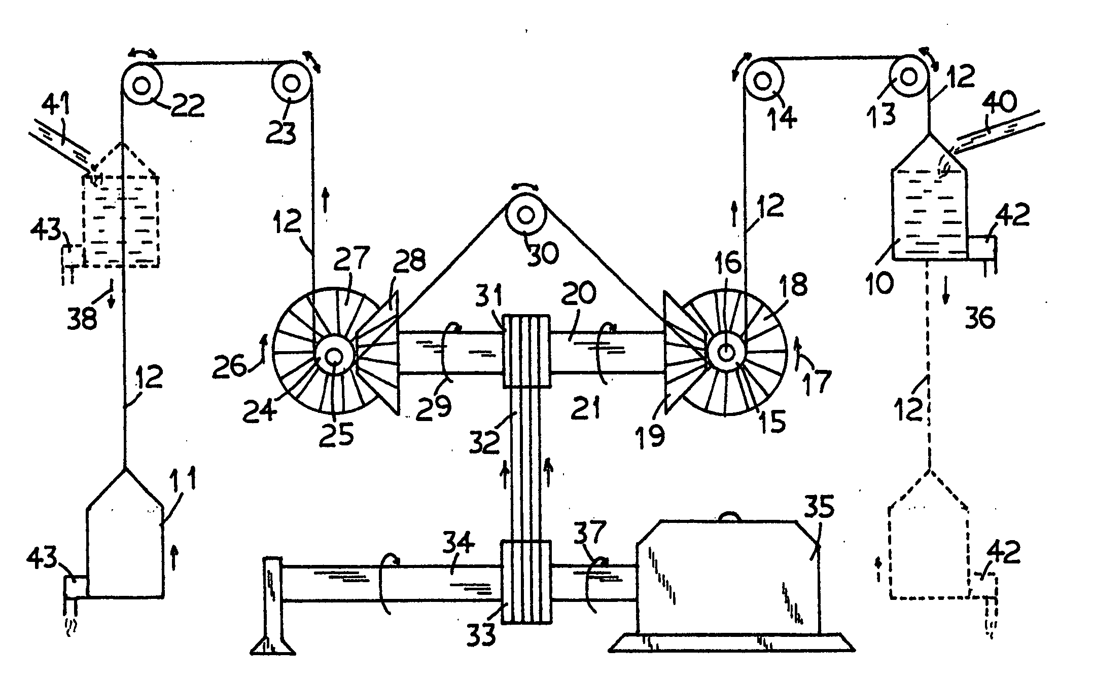
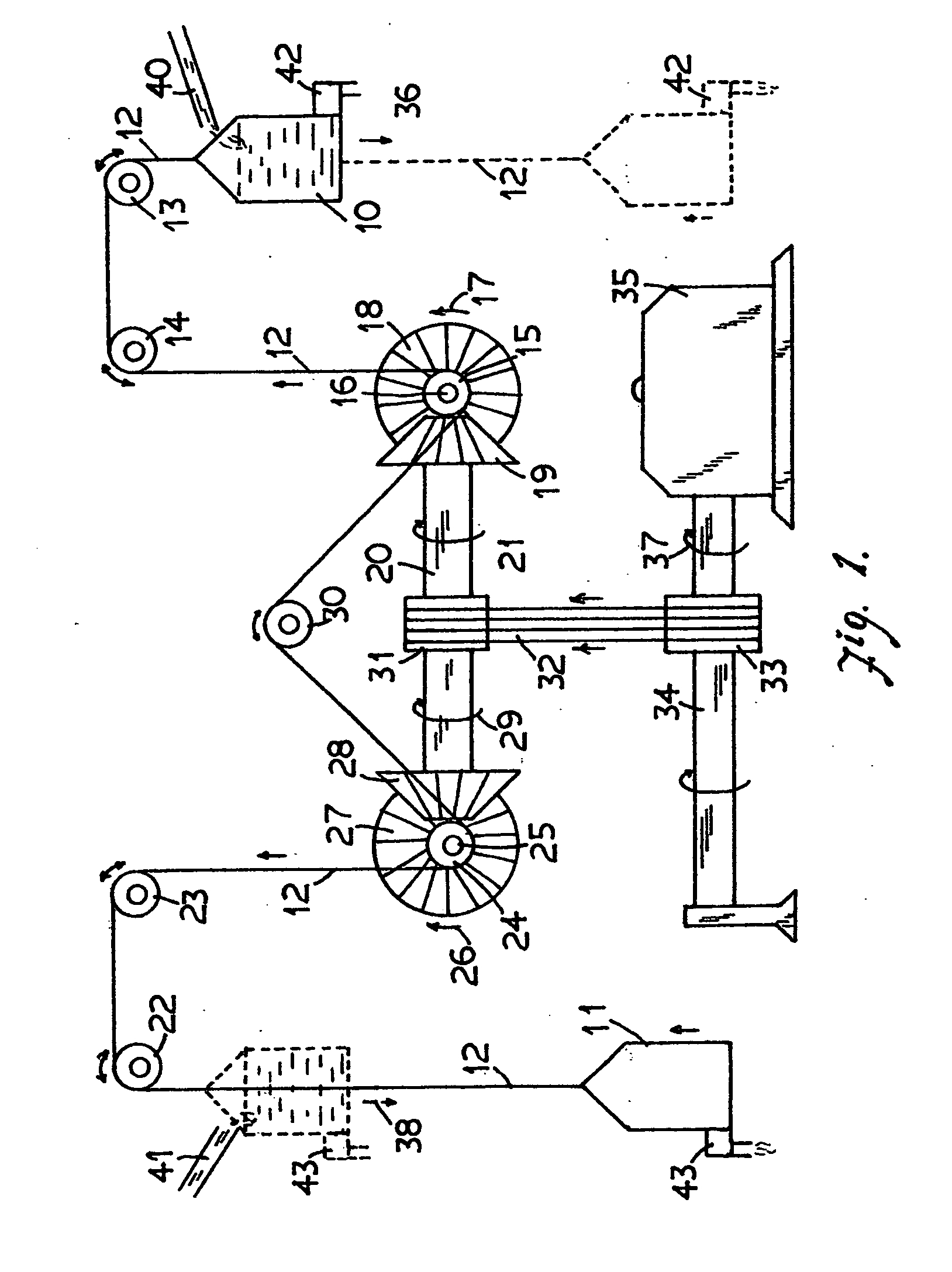
[0013] With reference to the drawings in which like reference numerals designate corresponding parts in the difference views, the basic system according to the present invention. As shown in FIG. 1, two water tanks 10 and 11 are suspended by an elongated band such as a chain or cable 12 at its two ends. The portion of the cable 12 coupled to the water tank 10 is supported by two freely rotatable pulleys 13 and 14 and then engages with a ratchet wheel 15 mounted on a rotary shaft 16. The ratchet wheel 15 meshes with the rotary shaft 16 when it rotates in the direction as shown by the arrow 17 and it will automatically disengages with the rotary shaft 16 when it rotates in the opposite direction to become a freely rotatable pulley. A bevel gear 18 is mounted on the rotary shaft 16. The bevel gear 18 engages with a complementary bevel gear 19 mounted on a drive shaft 20 such that when the rotary shaft 16, and in turn the bevel gear 18, rotates in the direction 17, the complementary bev...


PUM


Abstract

An electrical generator is driven by gravitational force provided by a plurality of pairs of water tanks. Each pair of water tanks is suspended by an elongated chain supported by a series of pulleys. The water tanks in each pair of water tanks move between an upper position and a lower position alternately by filling selected ones of the water tanks with water and draining from the other selected ones of the water tanks. The vertical movement of the water tanks alternately filled with water is translated by ratchet wheels and bevel gear wheels to rotate the electrical generator continuously for generating the electrical power.

Description

BACKGROUND OF THE INVENTION [0001] 1. Field of the Invention [0002] This invention relates to an alternative power generation system and more particularly relates to a mechanical system for converting gravitational force to electric power. The system utilizes pulleys driven by a variable weight provided by a renewable material such as water to create the gravitational force. [0003] 2. Background Art [0004] Electrical power is presently mainly produced by either fossil fuel, nuclear energy, or hydro energy. Fossil fuel such as coal is a non-renewable material which is depleting in an ever alarming increasing rate that it will soon become unavailable. Also, the burning of fossil fuel in the production of electrical power also produces numerous harmful pollution to the natural environment. On the other hand, nuclear power generation poses potential wide spread natural disasters in case of system accident or failure such as a melt down. The harmful effect from such disasters may last fo...

Claims


Application Information

Patent Timeline
Patent Type & Authority Applications(United States)
IPC IPC(8): F03B13/00H02P9/04
CPCF03B17/005Y02E10/20F03G7/10
Inventor CHIU, YU
Owner CHIU YU
Learn More