Phased array antenna including transverse circuit boards and associated methods

a phased array, transverse circuit board technology, applied in the field of antennas, can solve the problems of high signal loss of connectors typically used, added complexity and/or cost to antennas, and high cost of connectors used for interfaces, etc., to achieve the effect of reducing signal loss and being easy to assembl

Inactive Publication Date: 2007-07-05
HARRIS CORP
View PDF8 Cites 36 Cited by
  • Summary
  • Abstract
  • Description
  • Claims
  • Application Information

AI Technical Summary

Benefits of technology

[0007] In view of the foregoing background, it is therefore an object of the invention to provide a phased array antenna with an interface between the feed ne

Problems solved by technology

The interface between the feed network and the antenna elements typically comprises connectors and cabling, and the connectors typically used may suffer from high signal loss.
The connectors used for the interface may also be expensive and some antennas may require multiple connectors for each antenna element thereby adding complexity and/or cost to the antenna.
In addition, space

Method used


Image

  • Phased array antenna including transverse circuit boards and associated methods
  • Phased array antenna including transverse circuit boards and associated methods
  • Phased array antenna including transverse circuit boards and associated methods

Examples


Embodiment Construction

[0018] The invention will now be described more fully hereinafter with reference to the accompanying drawings, in which preferred embodiments of the invention are shown. This invention may, however, be embodied in many different forms and should not be construed as limited to the embodiments set forth herein. Rather, these embodiments are provided so that this disclosure will be thorough and complete, and will fully convey the scope of the invention to those skilled in the art. Like numbers refer to like elements throughout.

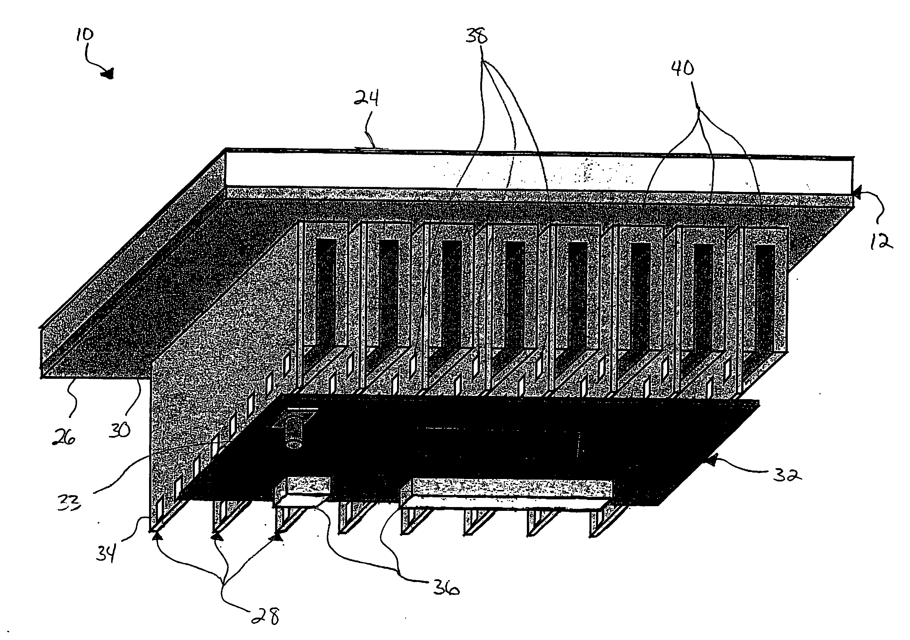
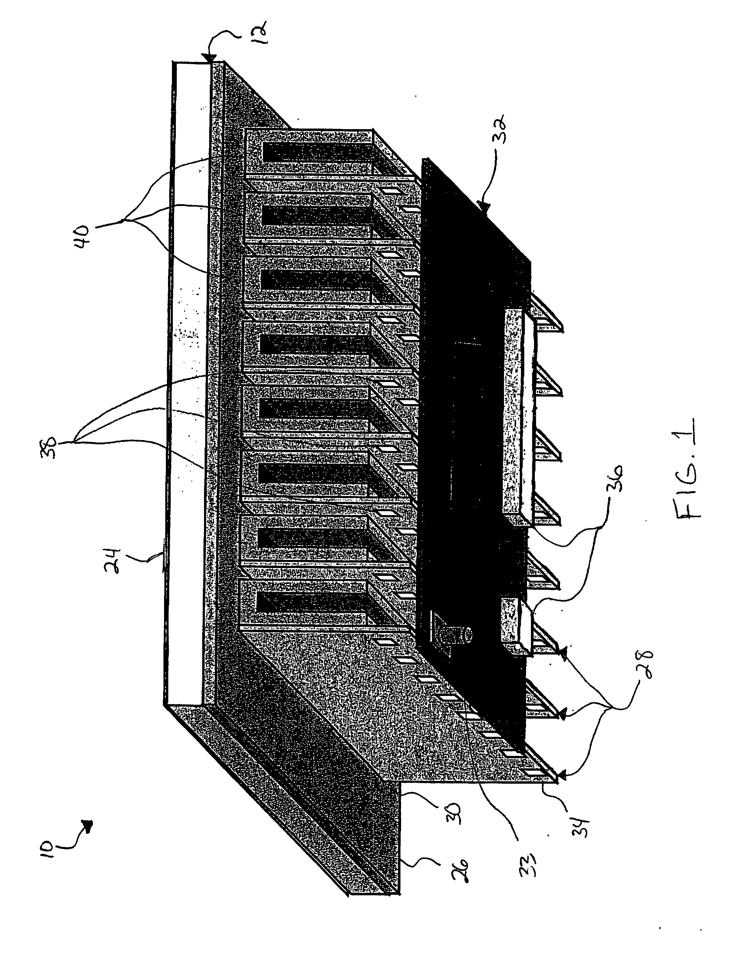
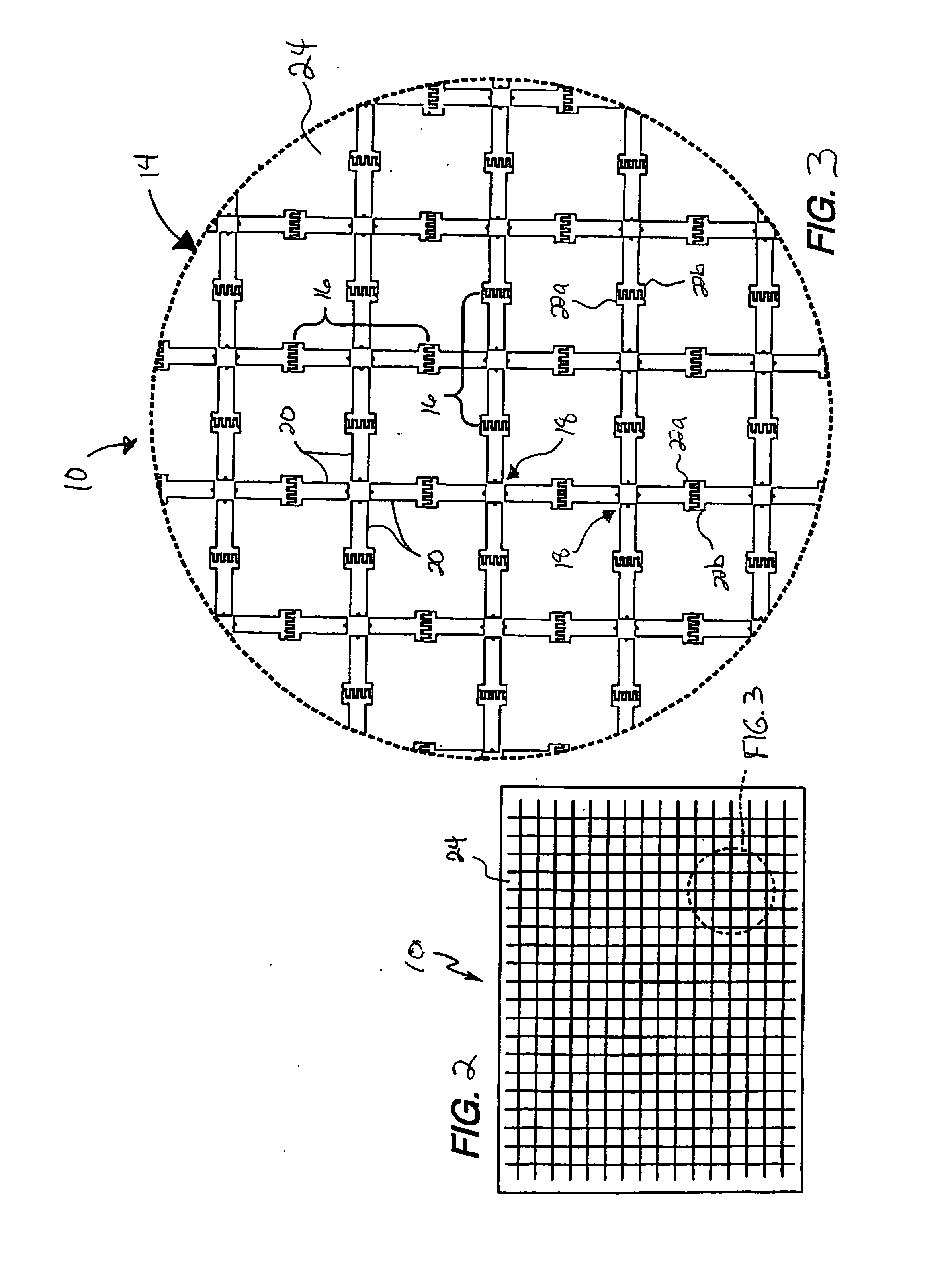
[0019] Referring to FIGS. 1-4, a phased array antenna 10 in accordance with the invention is now described. The phased array antenna 10 comprises a substrate 12 and a plurality of phased array antenna elements 14 carried by the substrate. The substrate 12 illustratively comprises a dielectric layer 24 carrying the phased array antenna elements 14 on a front surface thereof. An electrically conductive ground plane 26 is on a back surface of the dielectric layer 2...


PUM


Abstract

A phased array antenna may include a substrate and a plurality of phased array antenna elements carried by the substrate. A plurality of intermediate circuit boards may be arranged in spaced apart relation and each may extend transversely from the substrate. Each intermediate circuit board may have a forward end connected to a plurality of respective phased array antenna elements. A rear circuit board may be connected to the plurality of intermediate circuit boards at rearward ends thereof opposite the substrate.

Description

FIELD OF THE INVENTION [0001] The invention relates to the field of antennas, and, more particularly, to phased array antennas and related methods. BACKGROUND OF THE INVENTION [0002] A phased array antenna comprises a group of antenna elements in which the relative phases of the respective signals feeding the antenna elements are varied thereby controlling the radiation pattern of the phased array antenna. The interface between the feed network and the antenna elements typically comprises connectors and cabling, and the connectors typically used may suffer from high signal loss. The connectors used for the interface may also be expensive and some antennas may require multiple connectors for each antenna element thereby adding complexity and / or cost to the antenna. In addition, space limitations on the antenna may result in size limitations on the connectors and / or make the removal of heat difficult. [0003] U.S. Pat. No. 5,539,415 to Metzen et al. discloses a phased array device incl...

Claims


Application Information

Patent Timeline
IPC IPC(8): H01Q1/38
CPCH01Q21/062H01Q21/0087
Inventor HASH, RONALD J.TAYLOR, ROBERT C.JONES, ANTHONY MARKJANDZIO, GREGORY M.PALMER, WILLIAM R.
Owner HARRIS CORP
Why Eureka
Try Eureka