Microchannel apparatus comprising a platinum aluminide layer and chemical processes using the apparatus
a microchannel apparatus and platinum aluminide technology, applied in the direction of physical/chemical process catalysts, superimposed coating processes, chemical coatings, etc., can solve the problems of inability to report on the internal channel coating with platinum containing aluminides, microchannels, channels with bends, turns or other geometry complexity, etc., to reduce the corrosive power of chemical reaction, reduce the formation of coke, and reduce the effect of metal dus
- Summary
- Abstract
- Description
- Claims
- Application Information
AI Technical Summary
Benefits of technology
Problems solved by technology
Method used
Image
Examples
example 1
Electroless Plating of Tube Internals with Pt
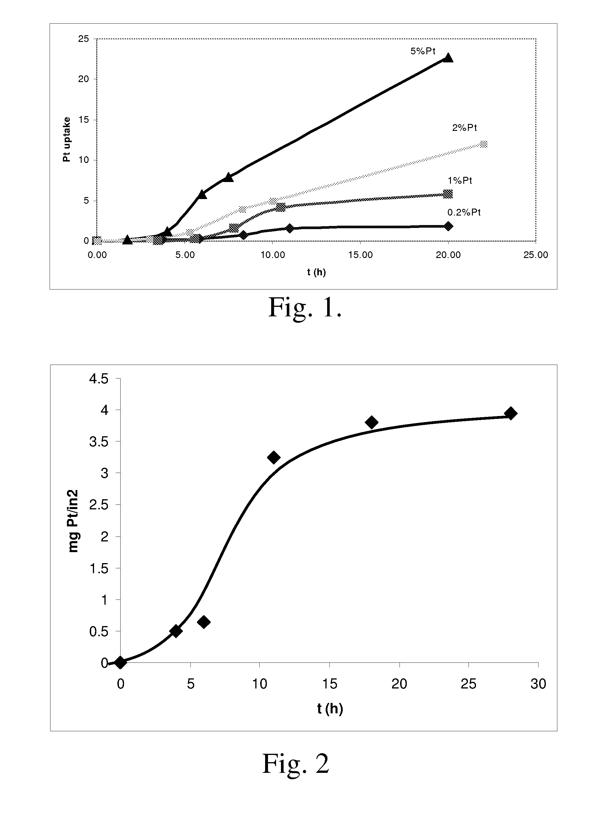
[0074] Stainless steel tubes have been used to demonstrate the effectiveness of electroless plating in coating internal surfaces of a channel with platinum. Tubes of ¼ inch and ⅛ inch outter diameter, 6 inches long have been used. Coating solution contains (NH3)4Pt(OH)2 and hydrazine in DI water, with the Pt metal to hydrazine ratio kept at 1:1 by weight. Plating was done at room temperature, by filling the tube with the solution and held static for a period of time. Multiple identical tubes were plated in parrallel, but terminated after different periods of time. After being rinsed with DI water and dried, the tubes were weighed and compared to the weights prior to the plating to deduce the platinum uptake. FIG. 1 gives the uptake by the ¼″ tubes as a function of time with solutions of different Pt concentrations. Note the uptake curves level off after ˜10 hr for 0.2 and 1% Pt solutions, suggesting depletion of the platinum precursor. T...
example 2
Electroless Plating of a Microchannel Device
[0075] A microchannel device was used to demonstrate the effectiveness of electroless plating of platinum. The device has two microchannels in parallel, in communication via a series of small holes (0.016-0.050 inch in diameter) along the channel length. Channel A has a total length of 24 inches and a cross section of 0.160 inch by 0.050 inch. It is of a U design with each arm of the U being 12 inch long. Channel B has a length of 6 inch and a cross section of 0.160 inch by 0.050 inch. An access is provided at the U for introduction of solution for electroless plating.
[0076] Electroless plating was done by filling the channels with a solution of (NH3)4Pt(OH)2 (5 wt % Pt) and hydrazine (5 wt %) in DI water at room temperature, letting the solution sit in the device for 20 hours, and followed by draining, rinsing, drying and final calcination at 450 C for 4 hr. The device was then autopsied and examined by optical and electron microscopies...
example 3
Downstream: Pt-Aluminide
[0078] A Ni-aluminide coupon (0.12 in×0.33 in×1.5 in), a Ni-aluminide spacer coupon (0.12 in×0.33 in×4.25 in) and a Pt-aluminide spacer coupon (0.12 in×0.33 in×4.25 in) were heated to 1050° C. in flowing H2 at 3.5° C. / min heating rate. After purging with Ar for 1 hour at 1050° C., the gas was changed to 21% O2 / Ar. The coupons were heat-treated in flowing O2 / Ar for 10 hours and then cooled to room temperature. An α-Al2O3 scale was generated on the surface after the heat treatment.
[0079] A platinum catalyst was coated onto the coupon electrolessly as follows. The heat-treated Ni-aluminide coupon (0.12 in×0.33 in×1.5 in) was hung in 50 g Pt(NH3)4(OH)2 solution containing 0.2 wt % Pt and 0.2 wt % N2H4H2O. The pH was adjusted to 11 by acetic acid. The solution was stirred for 24 hours at room temperature. After that, the coupon was rinsed with water and dried with blowing air. The coupon was then put in a new Pt solution with the same composition and the plating...
PUM
| Property | Measurement | Unit |
|---|---|---|
| angle | aaaaa | aaaaa |
| thick | aaaaa | aaaaa |
| thickness | aaaaa | aaaaa |
Abstract
Description
Claims
Application Information
 - R&D
- Intellectual Property
- Life Sciences
- Materials
- Tech Scout
- Unparalleled Data Quality
- Higher Quality Content
- 60% Fewer Hallucinations
Browse by: Latest US Patents, China's latest patents, Technical Efficacy Thesaurus, Application Domain, Technology Topic, Popular Technical Reports.
© 2025 PatSnap. All rights reserved.Legal|Privacy policy|Modern Slavery Act Transparency Statement|Sitemap|About US| Contact US: help@patsnap.com

