

Collapsible metal air battery
- Summary
- Abstract
- Description
- Claims
- Application Information
AI Technical Summary
Benefits of technology
Problems solved by technology
Method used
Image

Examples
embodiment 1
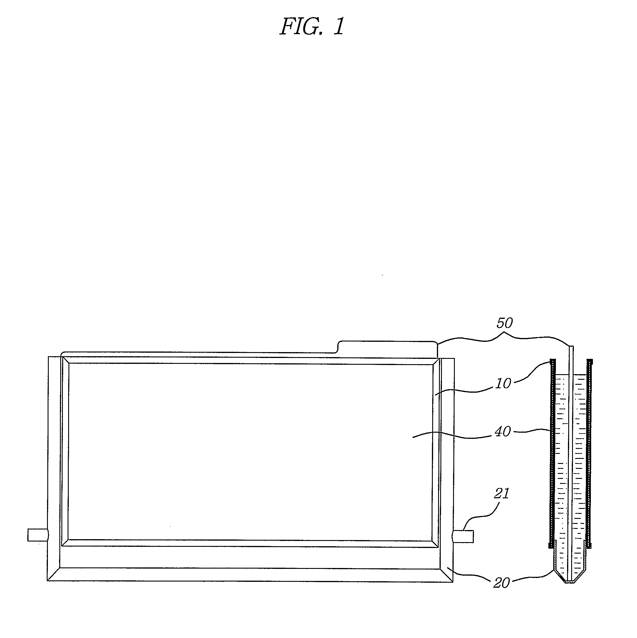
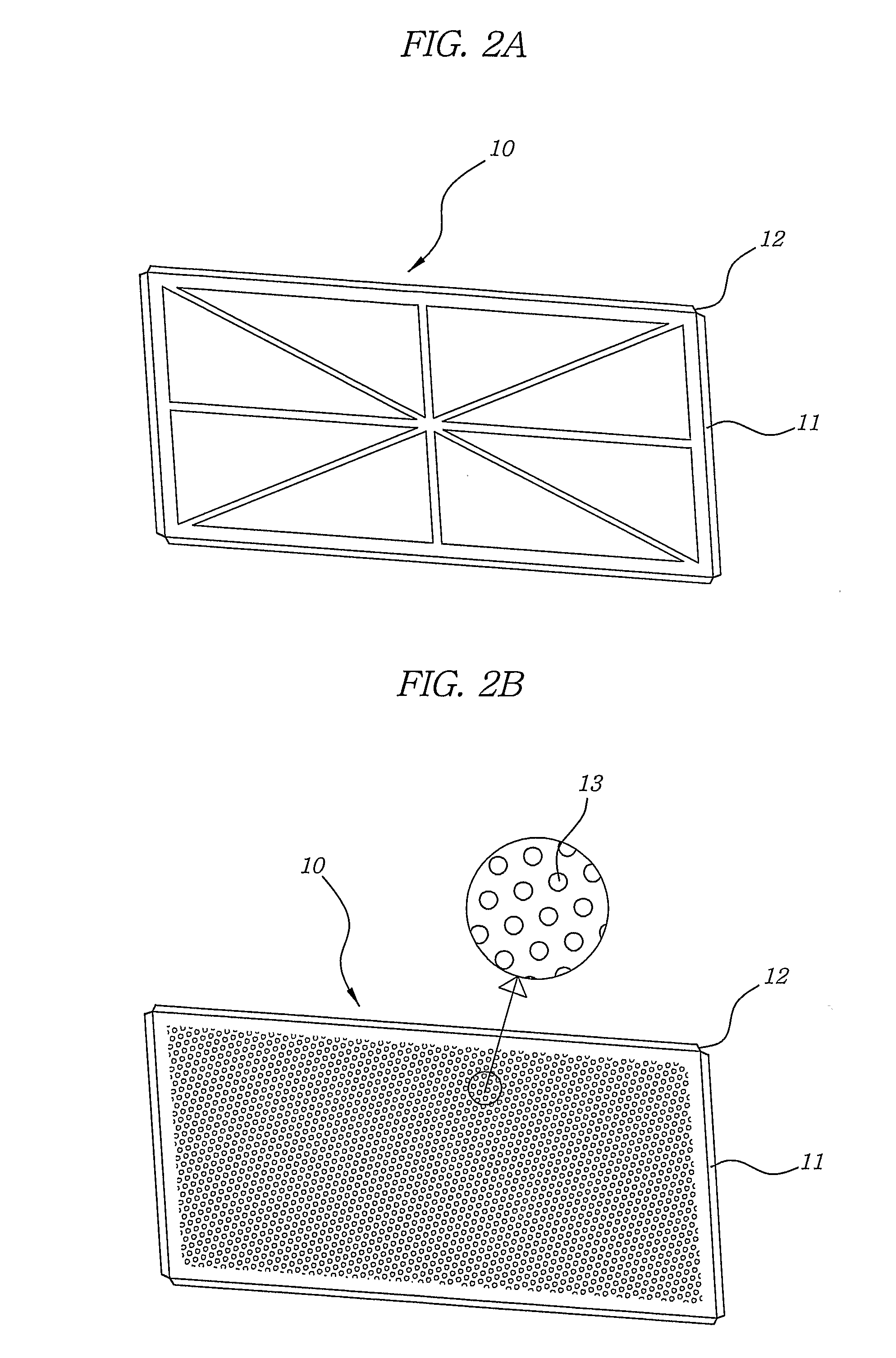
[0035] In the present invention, the metal frame 10 is rectangular metal frame formed of a window lattice shape such as a union jack shape or formed with punched holes. The four sides of the rectangular metal frames have bent portions 11 bent at 90°, and the four bent portions are draw-formed with a depth of 0.8˜1.2 mm. The four angular corners of the bent portions 10 are cut away at 45°, so that the four corners are not overlapped when folding the same.
[0036]FIG. 5 is an enlarged cross sectional view of a part of a unit cell fabricated using the metal frame 10 having a union jack shaped window lattice as shown in FIG. 2A. As shown therein, the separator 30 is adhered to the metal frame 10. Thereafter, the air cathode 40 coated with the carbon layer 41 and the hydrophobic layer 42 is adhered to the upper part of the separator 30. Here, the nickel mesh 43 of the air cathode 40 is disposed between the carbon layer 41 and the hydrophobic layer 42 and collects and transfer current. A a...
embodiment 2
[0037] In the present invention, the metal frame 10 is a rectangular metal frame formed of a window lattice shape such as a union jack shape or formed with punched holes. The four sides of the rectangular metal frames have bent portions 11 bent at 90°. FIG. 6 is an enlarged cross sectional view of a part of the unit cell fabricated using a metal frame having small punched holes 13 as shown in FIG. 2B. Here, the inner side of the metal frame 10 having a plurality of small holes with a diameter of 1mm operates as the nickel mesh. The punched holes 13 are formed based on a press and punching method. An active carbon powder same as the carbon layer 41 is filled into the interior of the metal frame 13. The inner side of the same operates as a path of air or oxygen. The adhesive is applied to an edge of the hydrophobic layer 42 in the same manner as the first embodiment of the present invention. The above air cathode may decrease the fabrication cost and a thickness of the metal air fuel ...
embodiment 3
[0038] The metal frame 10 is fabricated through a press compression and a cutting process. The metal frame 10 is a stainless steel plate (316 code) and a nickel plate (purity of 99.8%). The surface of the metal frame 10 is scratched based on a sand blasting method before the rubber glue is applied to the edge of the metal frame 10. A pair of metal frames 10 is inserted into the rubber mold and is cured at 180° C. under a pressure of 50 kg / cm2 for 60 seconds. Thereafter, the rubber housing is connected to a pair of the nickel frames. The air cathode 40 is O-Cat of the U.S. Evionyx Inc. As shown in FIGS. 5 and 6, it is coupled to the metal frame 10 together with the polypropylene separator 30. Any water leakage is not shown after a long time use of two weeks.
PUM
 Abstract
Description
Claims
Application Information