Handle system for deploying a prosthetic implant

a technology for prosthetic implants and catheters, applied in the field of medical devices, can solve the problems of affecting the safety of patients, so as to reduce the risk of aneurysms and improve the safety of patients. , the effect of reducing the kinking of the delivery catheter

Inactive Publication Date: 2007-07-05
CORDIS CORP
View PDF18 Cites 125 Cited by
  • Summary
  • Abstract
  • Description
  • Claims
  • Application Information

AI Technical Summary

Benefits of technology

[0013] A strain relief, formed for example from PTFE or polyethylene, joined to the first stationary portion at a distal tip of the handle system can alleviate kinking in the delivery catheter. For increased flexibility, the strain relief can have longitudinal ribs with longitudinal spaces therebetween. The longitudinal ribs define a generally conical outer surface, and support an inner cylinder, and may penetrate the inner cylinder and / or extend to the distal tip of the strain relief. Alternately, plural rows of openings extending a circumferential direction, preferably staggered in longitudinal and circumferential directions, can be provided

Problems solved by technology

Vascular disease is a leading cause of premature mortality in developed nations, often presenting as a vascular aneurysm.
If untreated, the aneurysm may burst and hemorrhage uncontrollably.
Aneurysms are particularly dangerous and prevalent in the aorta, because the aorta supplies blood to all other areas of the body, and because the aorta is subject to particularly high pressures and stresses accordingly.
Designing a viable stent graft for the treatment of abdominal aortic aneurysm (AAA) is particularly challenging, in part because the graft must branch to follow the shape of the abdominal aorta to carry blood into the separate iliac arteries without obstruction.
However, deployment in such vessels has proven challenging.
Moreover, part of that challenge has been the design of a handle system for a delivery catheter, operable by a surgeon at the proximal end of the delivery catheter which can deploy a stent graft implant remotely at the distal end of the delivery catheter.

Method used


Image

  • Handle system for deploying a prosthetic implant
  • Handle system for deploying a prosthetic implant
  • Handle system for deploying a prosthetic implant

Examples


Embodiment Construction

[0038] In a delivery system for a catheterized implant device, the implant, for example a stent or stent graft, is radially compressed onto an inner shaft or central core of the catheter. The implant and the inner shaft are then covered by an outer sheath, which restrains the implant during insertion into the body. Once delivered to the deployment site, the outer sheath is retracted, releasing the implant to expand to its deployed diameter. The location and deployment of the implant is controlled remotely at the proximal handle of the delivery catheter, minimizing trauma to the patient.

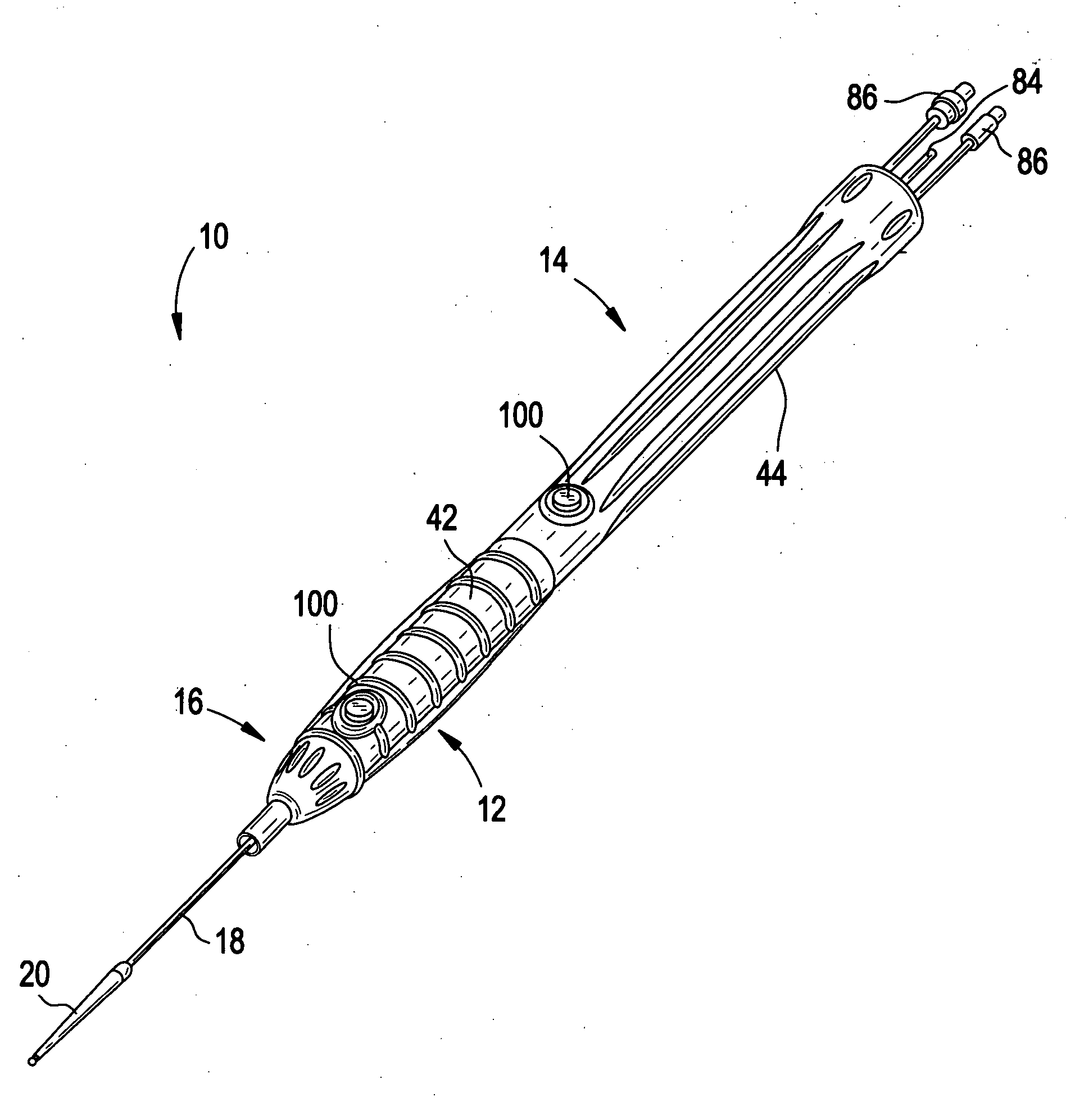
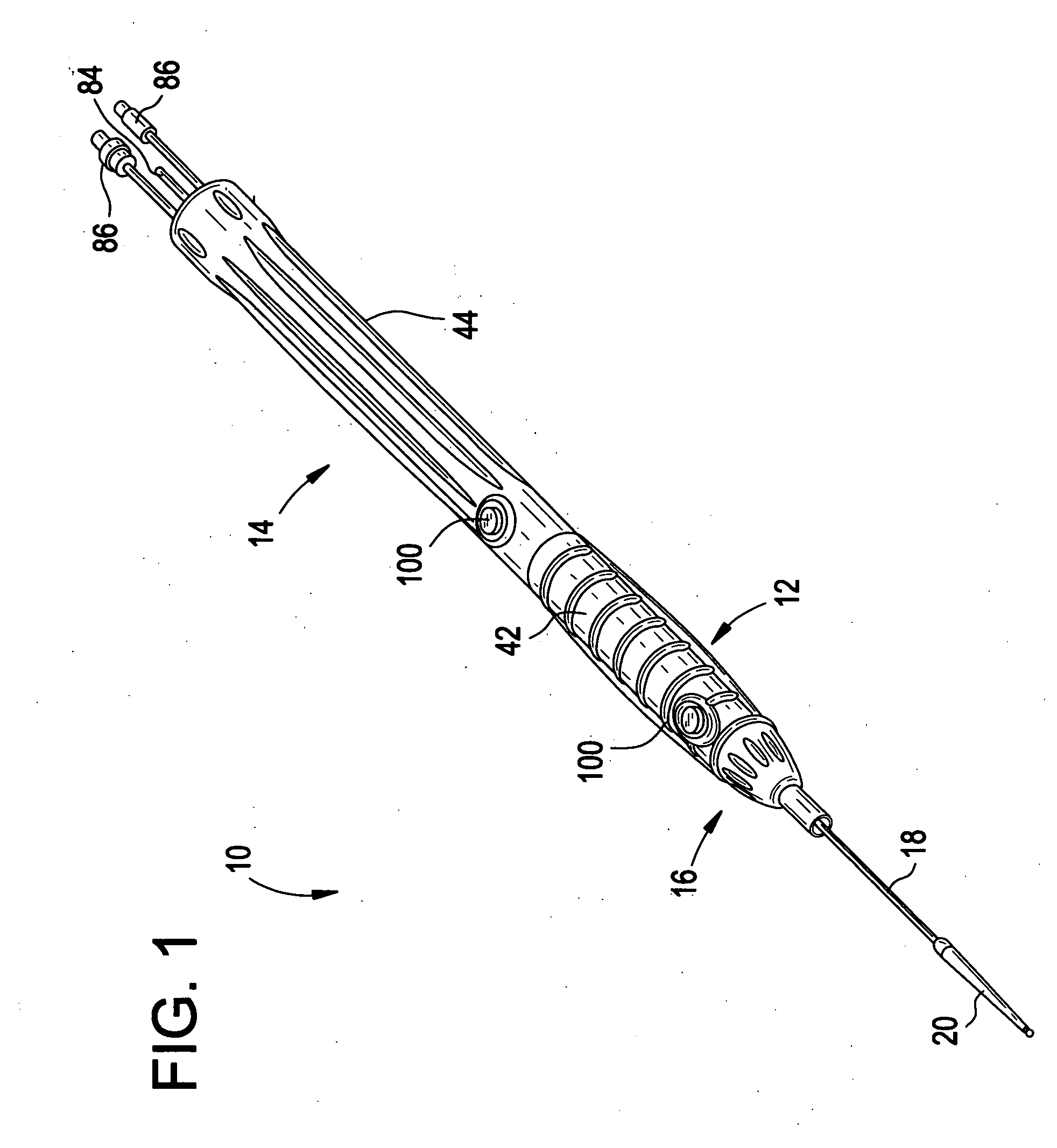
[0039] Referring now to FIG. 1, illustrated is a perspective view of the handle system, generally 10, according to a first embodiment of the present invention. Handle system 10 has a stationary portion 12 rotably connected to a rotating portion 14. Stationary portion 12 is considered stationary with respect to the handle system 10, and to the larger delivery catheter system of which the handle system...


PUM


Abstract

A handle system of a delivery catheter for the deployment of prosthetic implants includes a first stationary portion, at least one guide rail secured to the first stationary portion and extending generally longitudinally with the handle system, and a generally cylindrical second rotating portion rotably connected to the first stationary portion. A sheath mount is secured to an outer sheath of the delivery catheter, and includes one or more bearing surfaces to engage with at least one of the one or more guide rails. Rotation of the second rotating portion longitudinally displaces the sheath mount by interaction with the sheath mount. Interaction may be by internal thread of the rotating portion and external thread of the sheath mount, or alternately by rotating one or more drive screws by turning the rotating portion, the drive screws interacting with through holes in the sheath mount configured to receive and engage the drive screws.

Description

BACKGROUND OF THE INVENTION [0001] 1. Field of Invention [0002] The invention relates to the field of medical devices, and more particularly to a handle system of a catheter for the deployment of a prosthetic implant. [0003] 2. Description of Related Art [0004] Vascular disease is a leading cause of premature mortality in developed nations, often presenting as a vascular aneurysm. A vascular aneurysm is a localized dilation of a vessel wall, due to thinning or weakness of the wall structure, or separation between layers of the vessel wall. If untreated, the aneurysm may burst and hemorrhage uncontrollably. Aneurysms are particularly dangerous and prevalent in the aorta, because the aorta supplies blood to all other areas of the body, and because the aorta is subject to particularly high pressures and stresses accordingly. Rupture of an aortic aneurysm is the 15th leading cause of death in the United States, afflicting 5% of older men. [0005] Aortic aneurysms are described by their p...

Claims


Application Information

Patent Timeline
Patent Type & Authority Applications(United States)
IPC IPC(8): A61F2/06
CPCA61F2/95A61F2002/9517A61F2/966A61F2/9517
Inventor CIOANTA, IULIANRINCON, CESARWILKINS, BRIAN W.WINKLER, RANCE A.
Owner CORDIS CORP
Why Eureka
Try Eureka