
Method and apparatus for automatically detecting a latent referential integrity relationship between different tables of a database

a database and referential integrity technology, applied in the field of digital data processing, can solve the problems of large amount of system resources, complex processing resources, and large amount of processor resources, and achieve the effect of improving performan

Inactive Publication Date: 2007-07-05
IBM CORP
View PDF5 Cites 31 Cited by
  • Summary
  • Abstract
  • Description
  • Claims
  • Application Information

AI Technical Summary

Benefits of technology

[0029] By identifying queries capable of reduction based on latent referential integrity, the analytical tool provides valuable information to a database user which may be used to significantly improve performance not only of a current query instance but of numerous future query instances (or even unrelated queries of the same database).

Problems solved by technology

Such queries can consume significant system resources, particularly processor resources, and the speed at which queries are performed can have a substantial influence on the overall system throughput.
A query may be as simple as matching a single column field to a specified value, but is often far more complex, involving multiple field values and logical conditions.
Although the example above is a relatively simple one for illustrative purposes, it will be understood that a query could be, and often is, considerably more complex, containing multiple joins and conditions.
However, in many instances there exists a latent referential integrity relationship which is not defined by the designer or enforced by the database management software.
I.e., the data in the database may conform to the referential integrity constraints, even though there is no enforcement mechanism for assuring referential integrity.
In such cases, conventional optimizers are unable to reduce a join query of the type exemplified above because the optimizer does not know that the data conforms to the referential integrity constraints in advance of executing the query.

Method used


Image

  • Method and apparatus for automatically detecting a latent referential integrity relationship between different tables of a database
  • Method and apparatus for automatically detecting a latent referential integrity relationship between different tables of a database
  • Method and apparatus for automatically detecting a latent referential integrity relationship between different tables of a database

Examples


Embodiment Construction

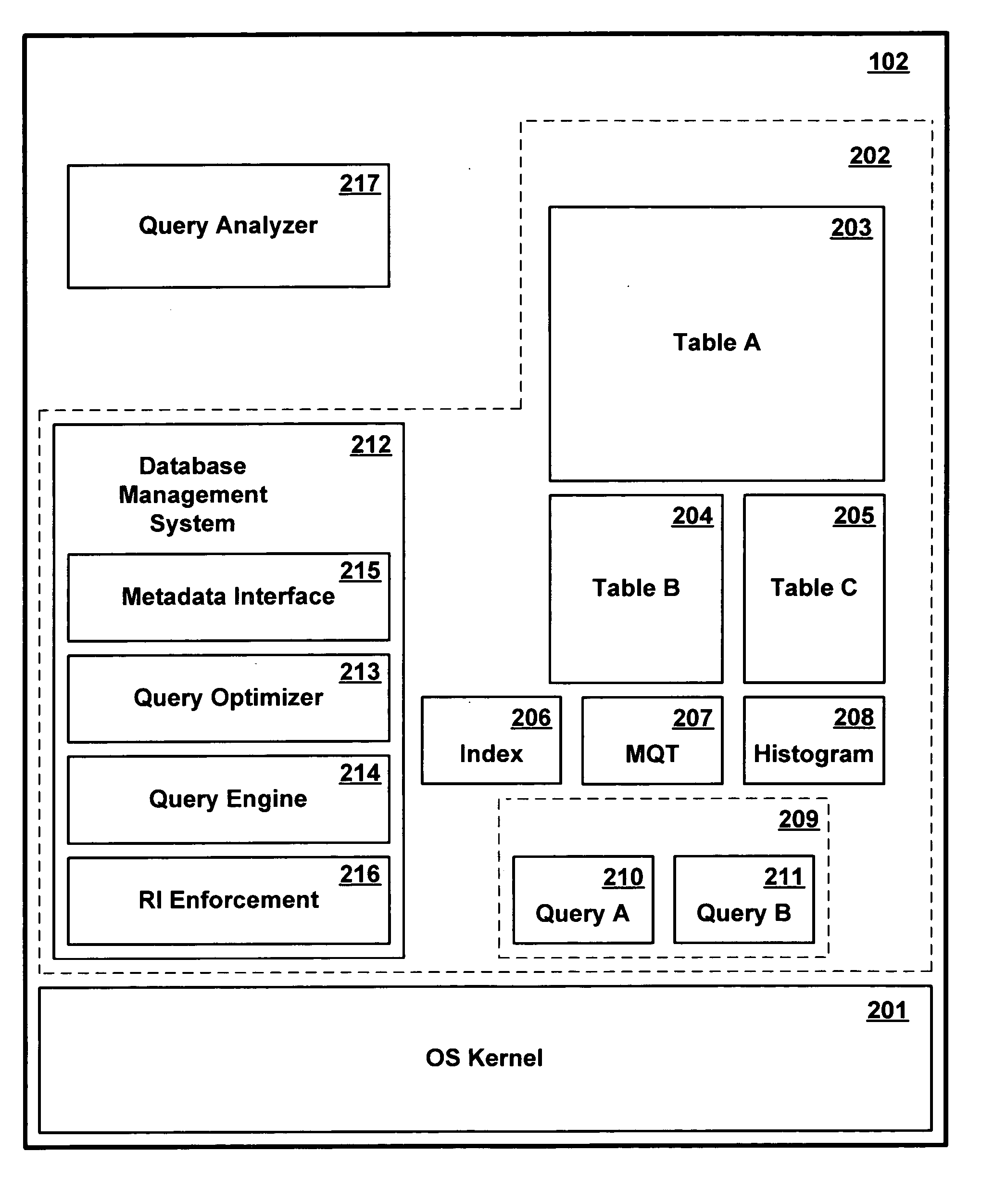
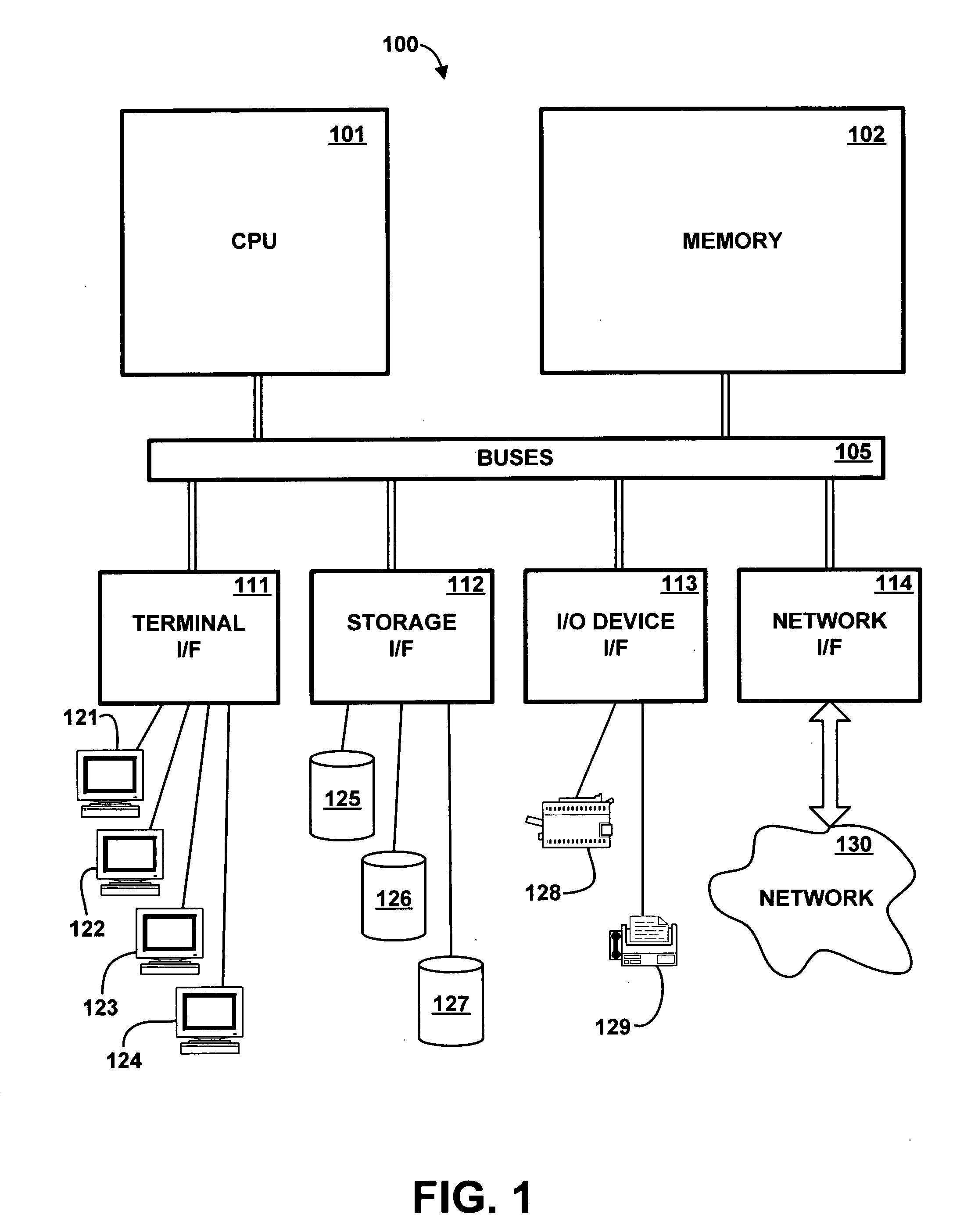
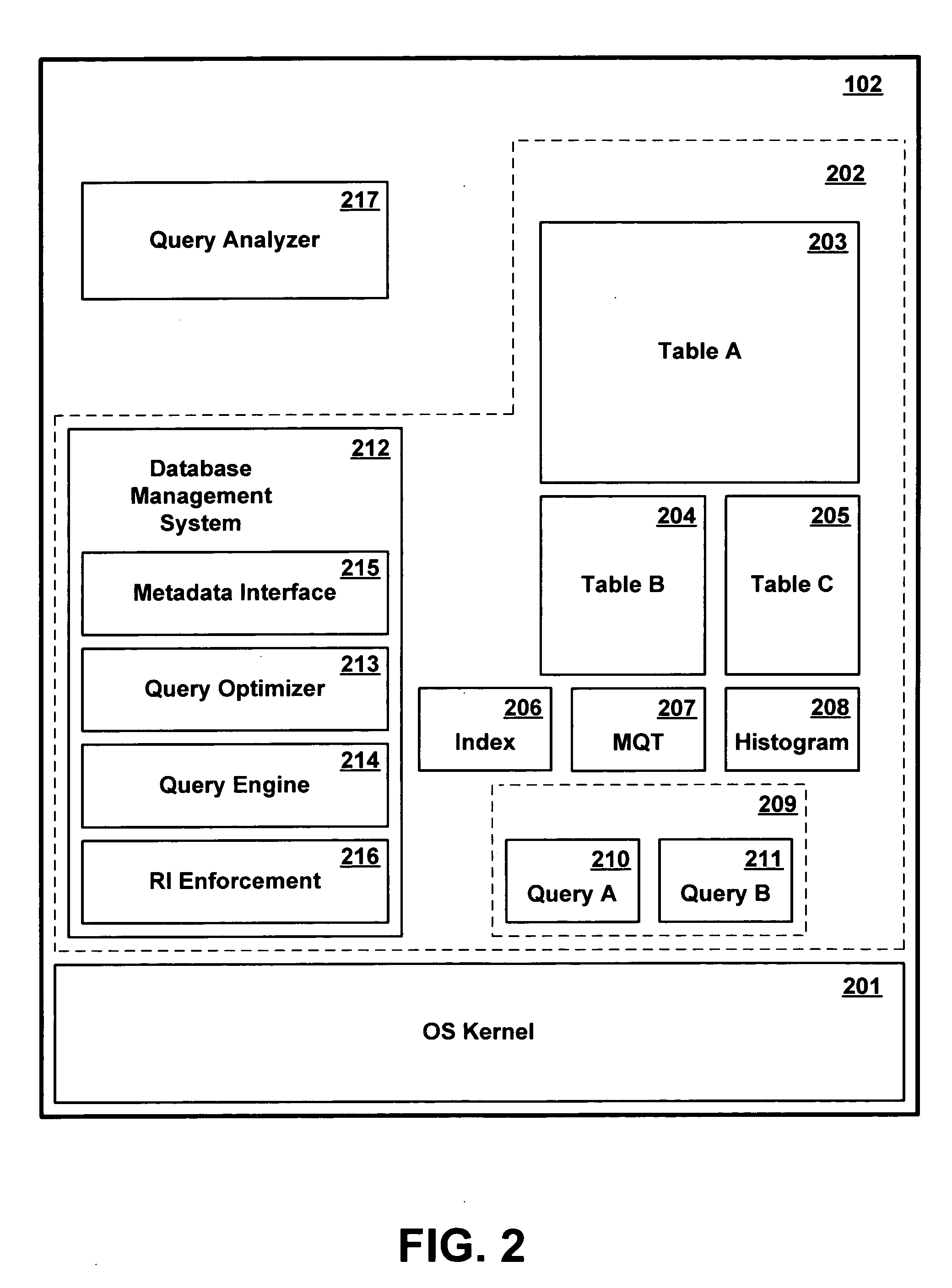
[0037] Referring to the Drawing, wherein like numbers denote like parts throughout the several views, FIG. 1 is a high-level representation of the major hardware components of a computer system 100 for use in generating and executing database queries, optimizing query strategies, and detecting a latent referential integrity relationship in a database, according to the preferred embodiment of the present invention. CPU 101 is at least one general-purpose programmable processor which executes instructions and processes data from main memory 102. Main memory 102 is preferably a random access memory using any of various memory technologies, in which data is loaded from storage or otherwise for processing by CPU 101.

[0038] One or more communications buses 105 provide a data communication path for transferring data among CPU 101, main memory 102 and various I / O interface units 111-114, which may also be known as I / O processors (IOPs) or I / O adapters (IOAs). The I / O interface units suppor...


PUM


Abstract

In one aspect, a database analytical tool or function analyzes join queries to detect queries which could be reduced if a referential integrity relationship were known. In another aspect, a probable latent referential integrity relationship is detected using one or more heuristics. Preferably, a join query is analyzed to detect a joined table which has no other conditions placed on it, and no referential integrity relationship already defined. For any such query, the analysis attempts to verify a probable latent referential integrity relationship using at least one heuristic, such as comparing cardinality of the potential primary key with the size of the table and / or with the cardinality of the foreign key. It is further possible to execute the join for some sample of records, and determine whether any records were found which did not conform to referential integrity constraints.

Description

FIELD OF THE INVENTION [0001] The present invention relates generally to digital data processing, and more particularly to the operation and maintenance of structured databases in a digital computer system. BACKGROUND OF THE INVENTION [0002] In the latter half of the twentieth century, there began a phenomenon known as the information revolution. While the information revolution is a historical development broader in scope than any one event or machine, no single device has come to represent the information revolution more than the digital electronic computer. The development of computer systems has surely been a revolution. Each year, computer systems grow faster, store more data, and provide more applications to their users. [0003] A modern computer system typically comprises hardware in the form of one or more central processing units (CPU) for processing instructions, memory for storing instructions and other data, and other supporting hardware necessary to transfer information,...

Claims


Application Information

Patent Timeline
IPC IPC(8): G06F7/00
CPCG06F17/30463G06F16/24542
Inventor BESTGEN, ROBERT JOSEPHKETHIREDDY, SHANTANPFEIFER, MICHAEL DONALD
Owner IBM CORP
Learn More