Power efficient flow through capacitor system

a capacitor and fluid technology, applied in the direction of electric circuits, manufacturing tools, electric circuits, etc., can solve the problems of increasing the wattage rating and cost of power supplies needed to provide power, the need to operate with a greater number of stages, and the need to reach a lower voltage limit, so as to reduce the amount of dead volume, reduce the need, cost and complication of connecting, and eliminate the need of connecting. , the effect of increasing the number of stages

Inactive Publication Date: 2007-07-12
BIOSOURCE INC
View PDF53 Cites 171 Cited by
  • Summary
  • Abstract
  • Description
  • Claims
  • Application Information

AI Technical Summary

Benefits of technology

[0006] The integrated stage design embodiment of the present invention eliminates the need, cost, and complication of connecting separate cartridge holders per stage by containing multiple stages within the same cartridge holder. This integrated stage design reduces the band broadening that would otherwise be caused by mixing of the band of purified water with dead volume as it moves from stage to stage. Staging efficiencies of 50% or more are possible by using sequential charge cycles coupled with integrated stage design. Another advantage achieved by organizing a flow-through capacitor system so that some or all stages are physically integrated is to diminish the amount of dead volume that otherwise exists between the capacitor layers and the inside the walls of the cartridge holder or capacitor container.
[0007] The integrated stage design of the present invention incrementally sharpens purified and concentrated bands of feed solution as it flows from stage to stage. In individually staged capacitors of the prior art, a dead volume exists between each multilayer capacitor cell and the internal walls of the housing of the cartridge holder. In the integrated stage embodiment, each stage shares common capacitor material layers. Only the current collectors, or, where electrodes are conductive enough not to need a current collector, the electrodes, are independently actuated and electrically separated from each other. Therefore, multiple stages can share the same cartridge holder, thereby eliminating the need for separate current collectors. Eliminating excess dead volume through integrated staging allows operation of the capacitor at lower voltage while, at the same time, obtaining a deep purification peak. The result of this is that the capacitor may be operated at lower, more energy efficient voltages.

Problems solved by technology

The mixing effect also leads to a need to operate with greater numbers of stages, and may reach a lower voltage limit, as voltage is lowered when used with concentrated water such as sea water.
Charging banks or stages of capacitors all at once multiplies this peak power, thereby increasing the wattage rating and cost of power supplies needed to provide this power.

Method used


Image

  • Power efficient flow through capacitor system
  • Power efficient flow through capacitor system
  • Power efficient flow through capacitor system

Examples


Embodiment Construction

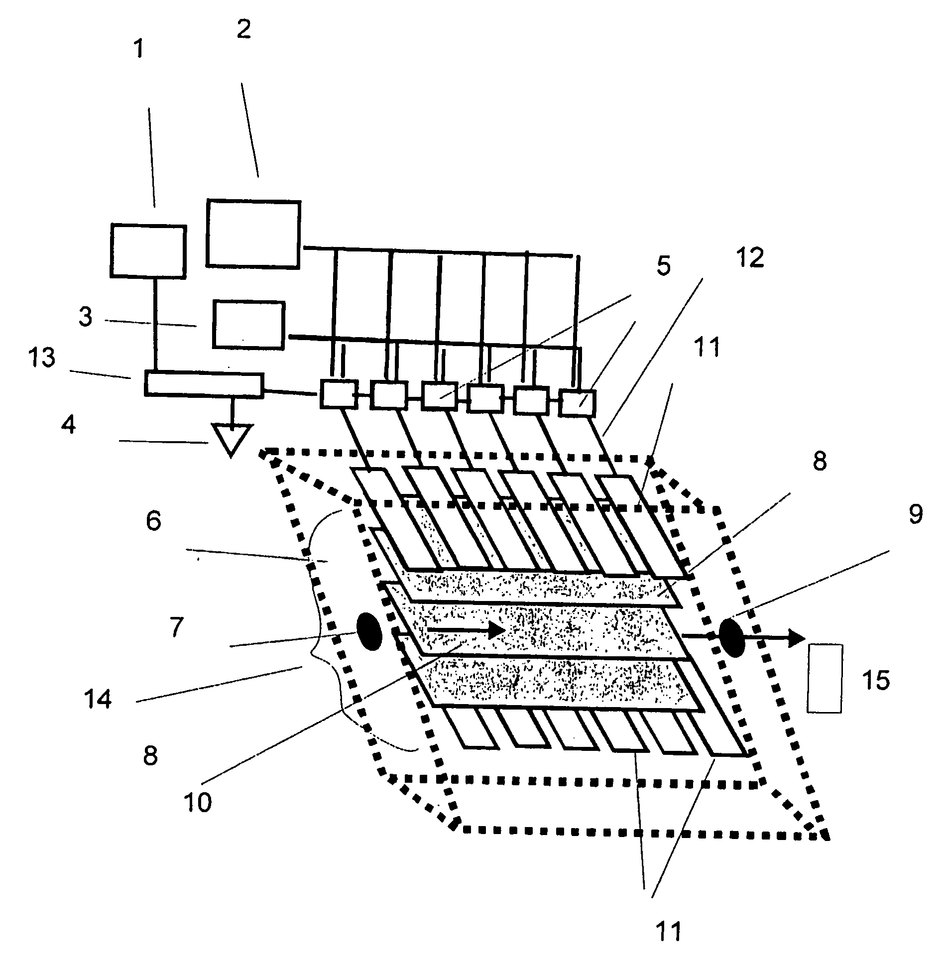
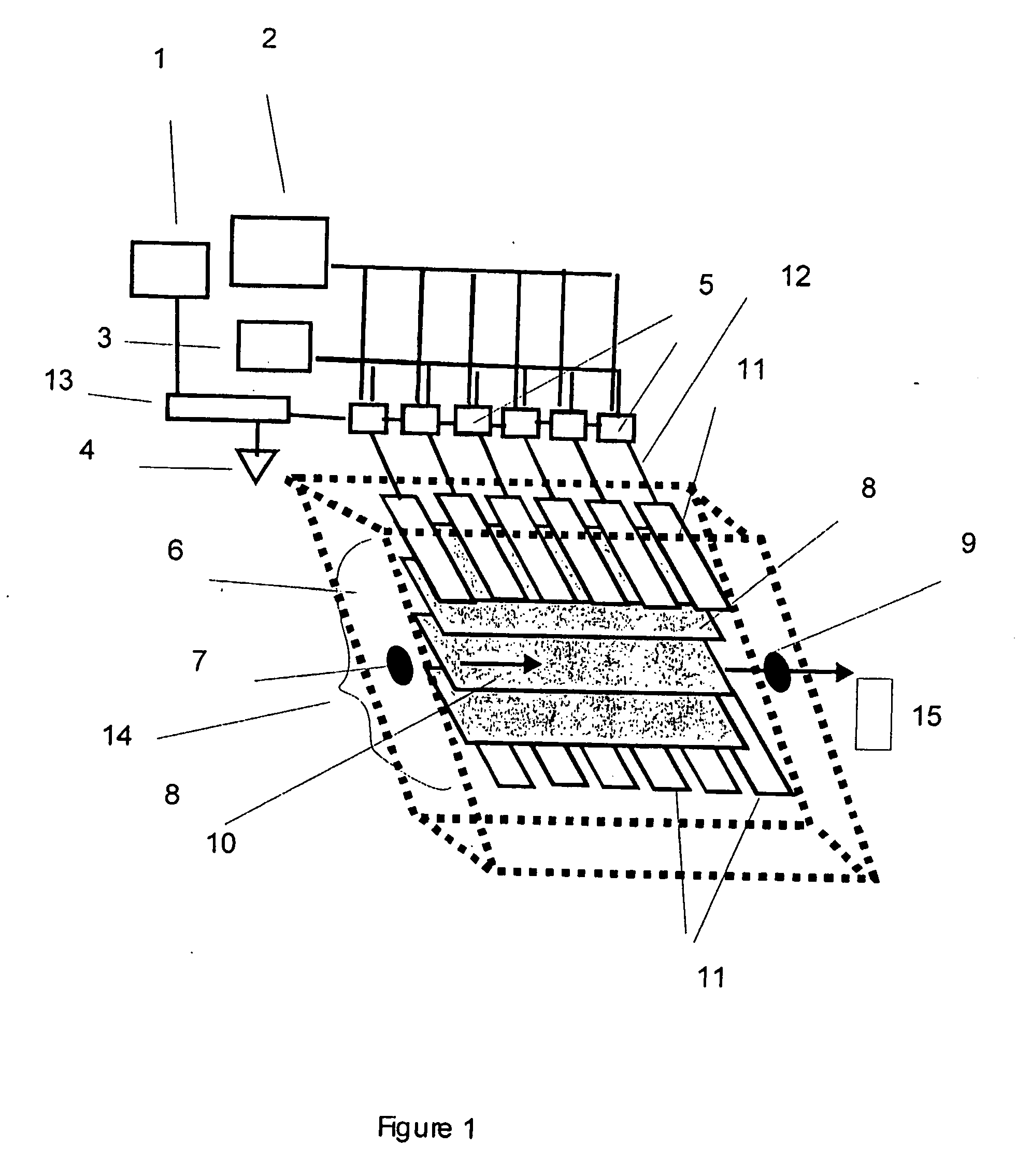
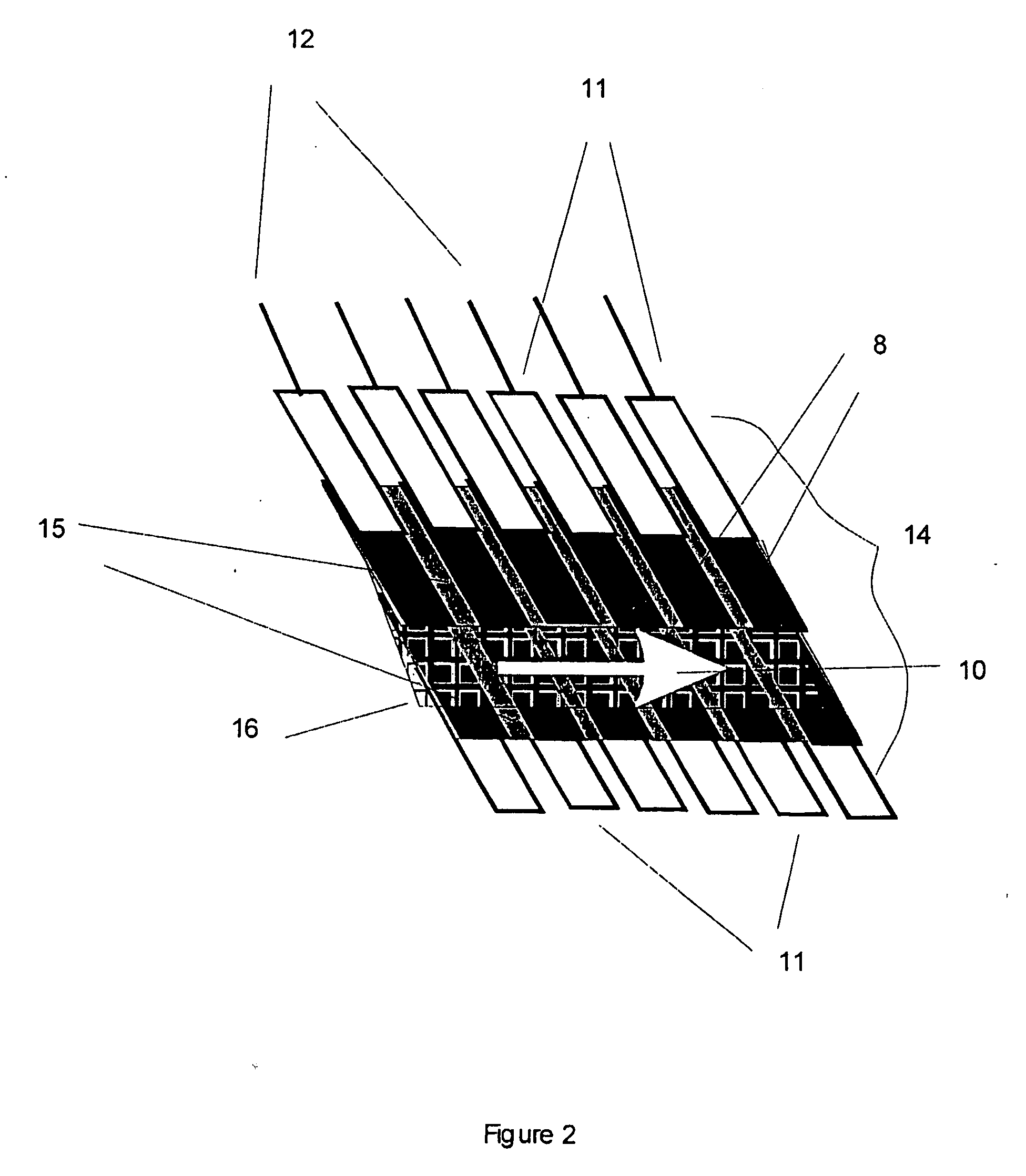
[0024]FIG. 1 is a schematic of an integrated stage flow-through capacitor cell and system of the present invention, showing a controller or logic means 1, a power supply 2, e.g., a capacitor power supply, a switch power supply 3, ground 4, switches, relays, or FETS, e.g., switches 5, a cartridge or cell holder 6 as a casing for one or more capacitor cells, inlet 7, electrode or electrode assembly 8, outlet 9, flow path 10, individual current collector 11, individual current collector lead 12, circuit 13, e.g., an integrated circuit, programmable logic chip, digital input / out, or printed circuit; cell assembly 14, and sensor 15. A computer or controller 1 and a additional digital input / output 13 controls and actuates switches, relays, or FETS 5 in either a pre-programmed or feed-back controlled sequence using conductivity, pH, or other composition data, or flow, amperage, or voltage data supplied to controller 1 by sensor 15. Switch 5 can be multiple switching, and can also be an int...


PUM

PropertyMeasurementUnit
diameteraaaaaaaaaa
contact resistanceaaaaaaaaaa
voltageaaaaaaaaaa

Abstract

The invention features a flow-through capacitor system that achieves enhanced power efficiency by sequential control and actuation of at least two or more flow-through capacitor cells within the flow-through capacitor system. Alternatively or in addition, power efficiency is enhanced by integrating the purification stages of the system, for example, by placing more than one cell within a single cell casing. Preferably, integrated stage flow-through capacitors are controlled sequentially.

Description

REFERENCE TO PRIOR APPLICATION [0001] This application is based on and claims priority from U.S. provisional patent application Ser. No. 60 / 492,938, filed Aug. 6, 2003, which is hereby incorporated by reference.FIELD OF THE INVENTION [0002] The field of the invention is systems for capacitive deionization of fluids by the use of flow through capacitors. BACKGROUND OF THE INVENTION [0003] It is generally recognized that, in order to purify concentrated water, flow-through capacitor purification systems need to be staged. It is an objective of the present invention to improve the staging and power efficiency of flow-through capacitors. Power efficiency is a measure of how well power is distributed in a multi-cell system, and is defined here as the averaged percent of power needed by a flow-through capacitor system divided by the system's peak power needs. Staging efficiency is a measure of how well a staged system is designed to limit the inter-stage mixing caused by inter-stage dead ...

Claims


Application Information

Patent Timeline
Patent Type & Authority Applications(United States)
IPC IPC(8): C25B9/18H01G
CPCC02F1/4604C02F1/4691C02F2001/46152C02F2209/005C02F2201/4611C02F2201/4613C02F2201/4615C02F2103/08
Inventor ANDELMAN, MARC D.KURAN, SHIHABZULKIEWICZ, JON
Owner BIOSOURCE INC
Why Eureka
Try Eureka