
Dynamic random access memory structure and method for preparing the same

a random access memory and dynamic technology, applied in the direction of semiconductor devices, electrical apparatus, transistors, etc., can solve the problems of the retention time of the carriers, and achieve the effects of increasing integrity, reducing the storage area, and reducing the storage tim

Active Publication Date: 2007-07-12
PROMOS TECH INC
View PDF10 Cites 41 Cited by
  • Summary
  • Abstract
  • Description
  • Claims
  • Application Information

AI Technical Summary

Benefits of technology

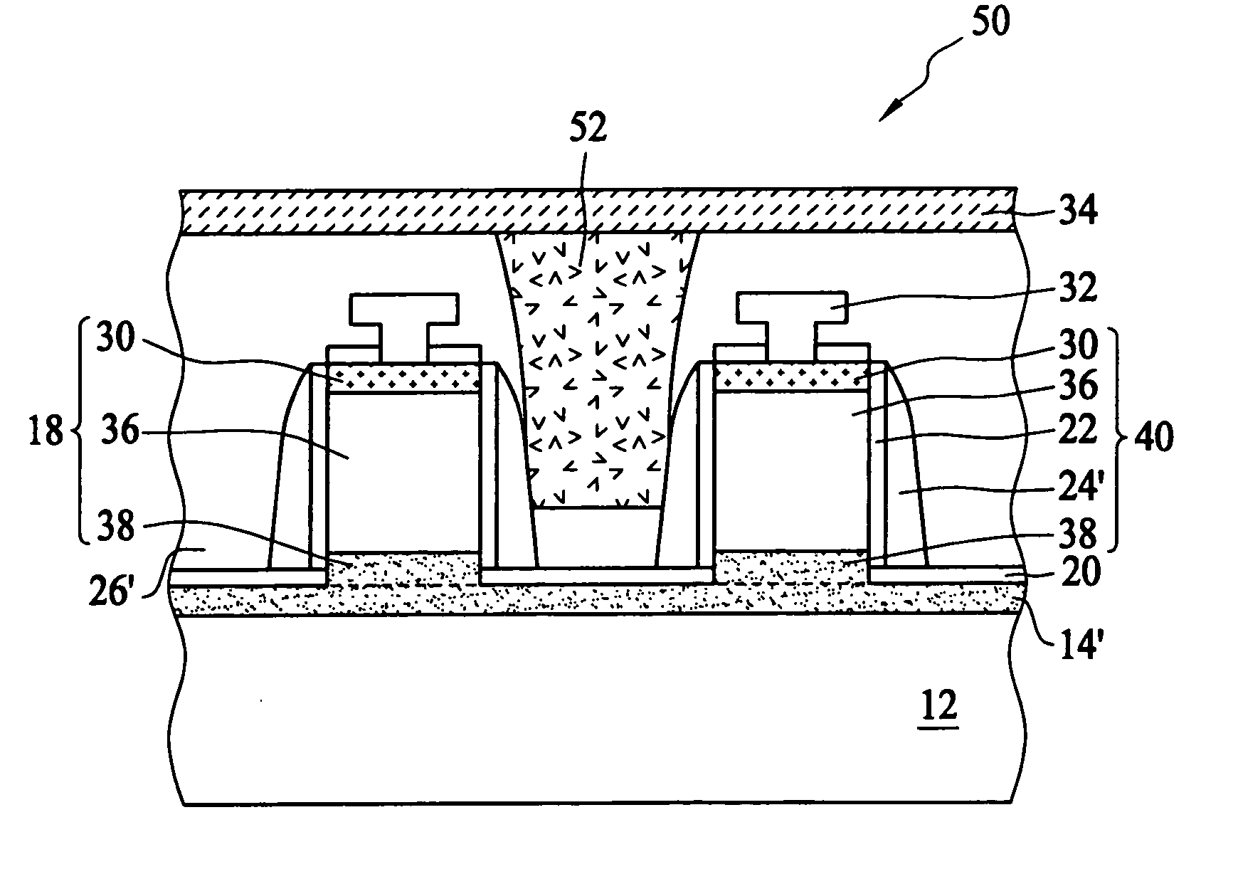
[0007] The primary objective of the present invention is to provide a dynamic random access memory structure having vertical floating body memory cells and method for preparing the same, which stores the carriers in the center of a vertically disposed floating body rather than in an interface between different material so as to have a longer retention time to the prevention of the recombination of the carrier with defects in the interface.
[0011] The conventional floating body cell is horizontally positioned and prepared on an expensive SOI substrate. Inversely, the dynamic random access memory structure of the present invention possesses one advantage of occupying a smaller area for increasing integrity since the floating body memory cell is vertically positioned. Further, the stored carriers stay in most cases at the center of the cylindrical body, which is not likely to recombine with the defects in the interface such as the surface of the pillar; hence, the carriers will have a longer retention time according to the present invention. In addition, the preparation of the vertical floating body memory cell can use the silicon substrate and the LOCOS process to form silicon on insulator structure rather than using the expensive SOI substrate as the prior art does; therefore, the present invention can dramatically decrease the fabrication cost.

Problems solved by technology

However, the floating body cell stores the carriers around an interface between two different materials, and defects in the interface is likely to recombine with the carriers, which influences the retention time of the carriers in the floating body.

Method used


Image

  • Dynamic random access memory structure and method for preparing the same
  • Dynamic random access memory structure and method for preparing the same
  • Dynamic random access memory structure and method for preparing the same

Examples


Embodiment Construction

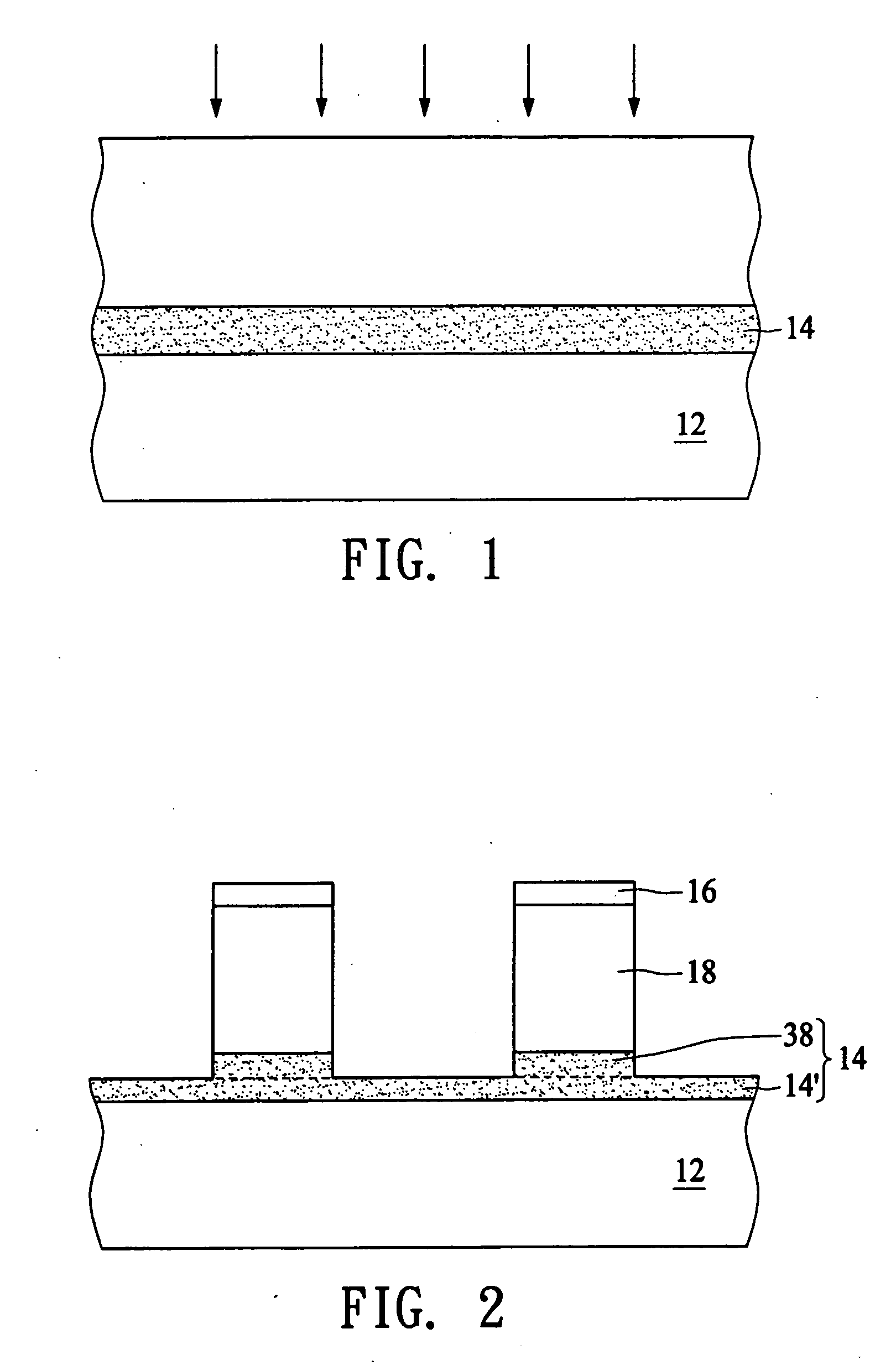
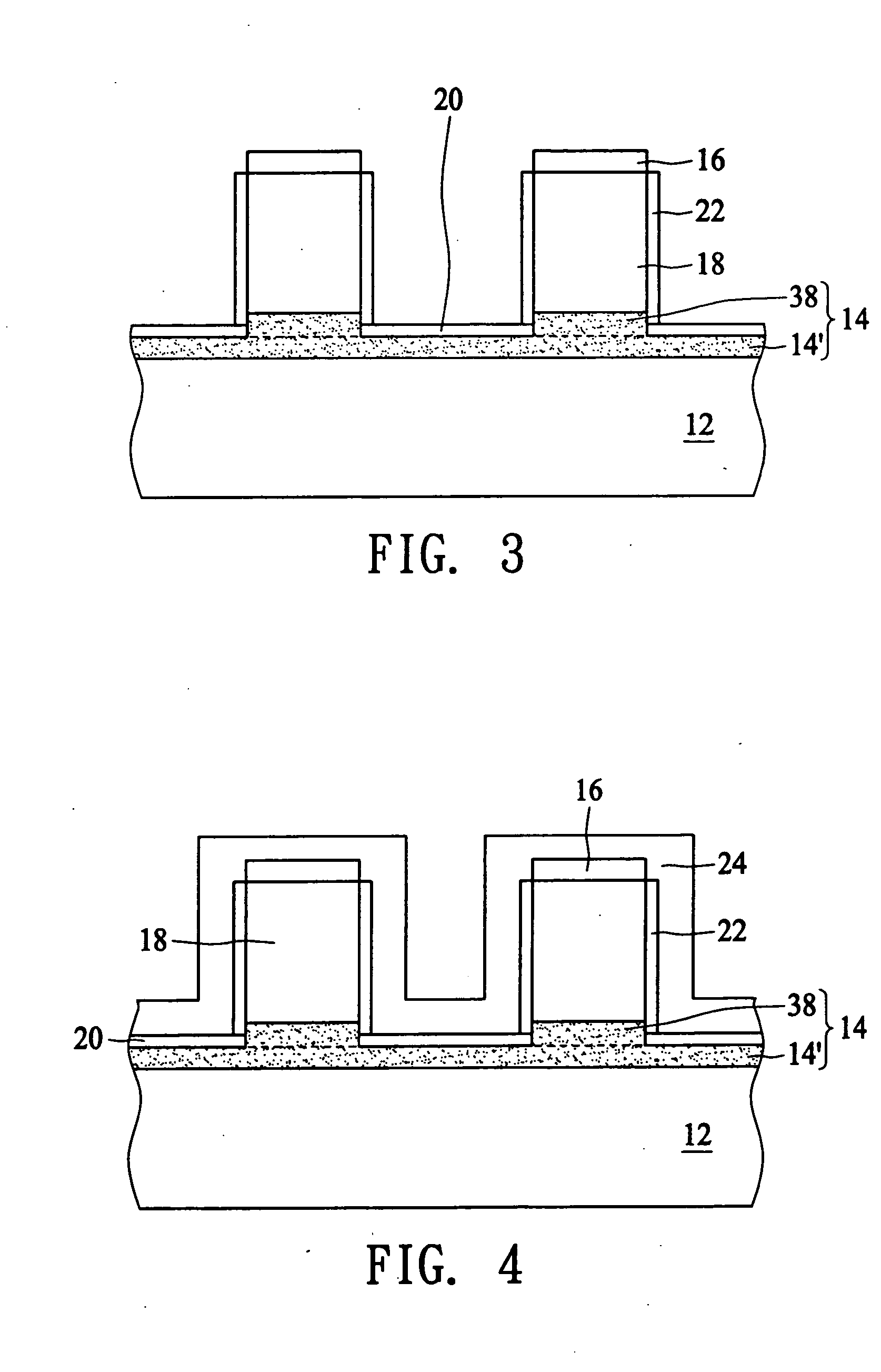
[0017]FIG. 1 to FIG. 6 illustrate a method for preparing a dynamic random access memory structure 10 according to one embodiment of the present invention. First, an implanting process is performed to implant ions into a predetermined depth in a semiconductor substrate 12 such as a silicon substrate to form a conductive layer 14 in the semiconductor substrate 12. Subsequently, a mask layer 16 is formed on the semiconductor substrate 12 and an etching process is then performed to remove a portion of the semiconductor substrate 12 not covered by the mask layer 16 down to the interior of the conductive layer 14 in the semiconductor substrate 12 to form a plurality of cylindrical pillars 18. Particularly, the conductive layer 14 can be regarded as two portions, i.e., a bottom conductive region 38 at the bottom portion of the cylindrical pillar 18 and a conductive layer 14′ on the surface of the semiconductor substrate 12, as shown in FIG. 2.

[0018] Referring to FIG. 3, a deposition proce...


PUM

PropertyMeasurementUnit
conductiveaaaaaaaaaa
sizeaaaaaaaaaa
read out voltageaaaaaaaaaa

Abstract

A dynamic random access memory structure having a vertical floating body cell includes a semiconductor substrate having a plurality of cylindrical pillars, an upper conductive region positioned on a top portion of the cylindrical pillar, a body positioned below the upper conductive portion in the cylindrical pillar, a bottom conductive portion positioned below the body in the cylindrical pillar, a gate oxide layer surrounding the sidewall of the cylindrical pillar and a gate structure surrounding the gate oxide layer. The upper conductive region serves as a drain electrode, the bottom conductive region serves as a source electrode and the body can store carriers such as holes. Preferably, the dynamic random access memory structure further comprises a conductive layer positioned on the surface of the semiconductor substrate to electrically connect the bottom conductive regions in the cylindrical pillars.

Description

BACKGROUND OF THE INVENTION [0001] (A) Field of the Invention [0002] The present invention relates to a dynamic random access memory (DRAM) structure and method for preparing the same, and more particularly, to a dynamic random access memory structure having vertical floating body memory cells and method for preparing the same. [0003] (B) Description of the Related Art [0004] A memory cell of the DRAM generally consists of a metal oxide semiconductor field effect transistor and a capacitor on a silicon substrate, and the transistor includes a source electrode electrically connected to an upper storage plate of the capacitor. There are two types of capacitors: stack capacitors and deep trench capacitors. The stack capacitor is fabricated on the surface of the silicon substrate, while the deep trench capacitor is fabricated inside the silicon substrate. Recently, the integrity of the DRAM has increased with the innovation of semiconductor fabrication technology rapidly. However, the s...

Claims


Application Information

Patent Timeline
Patent Type & Authority Applications(United States)
IPC IPC(8): H01L29/94
CPCH01L29/7841H10B12/20H10B12/00
Inventor WANG, TING SING
Owner PROMOS TECH INC
Learn More