Metal halide lamp and luminaire using the same

a technology of metal halide lamps and luminaires, which is applied in the direction of fixed installations, gas-filled discharge tubes, lighting and heating apparatus, etc., can solve the problems of unexpected problems and deterioration of quality in appearance, and achieve the effect of preventing a decline in lumen maintenance and a deterioration of quality in appearance, and high luminous efficiency

Inactive Publication Date: 2007-07-12
PANASONIC CORP
View PDF5 Cites 11 Cited by
  • Summary
  • Abstract
  • Description
  • Claims
  • Application Information

AI Technical Summary

Benefits of technology

[0007] The present invention was made in order to solve these new issues that did not occur with a conventional ceramic metal halide lamp. The first objective of the present invention is to provide a metal halide lamp having the following characteristics: (i) to preven...

Problems solved by technology

This examination revealed unexpected issues.
Along with a decline i...

Method used


Image

  • Metal halide lamp and luminaire using the same
  • Metal halide lamp and luminaire using the same
  • Metal halide lamp and luminaire using the same

Examples


first embodiment

1. First Embodiment

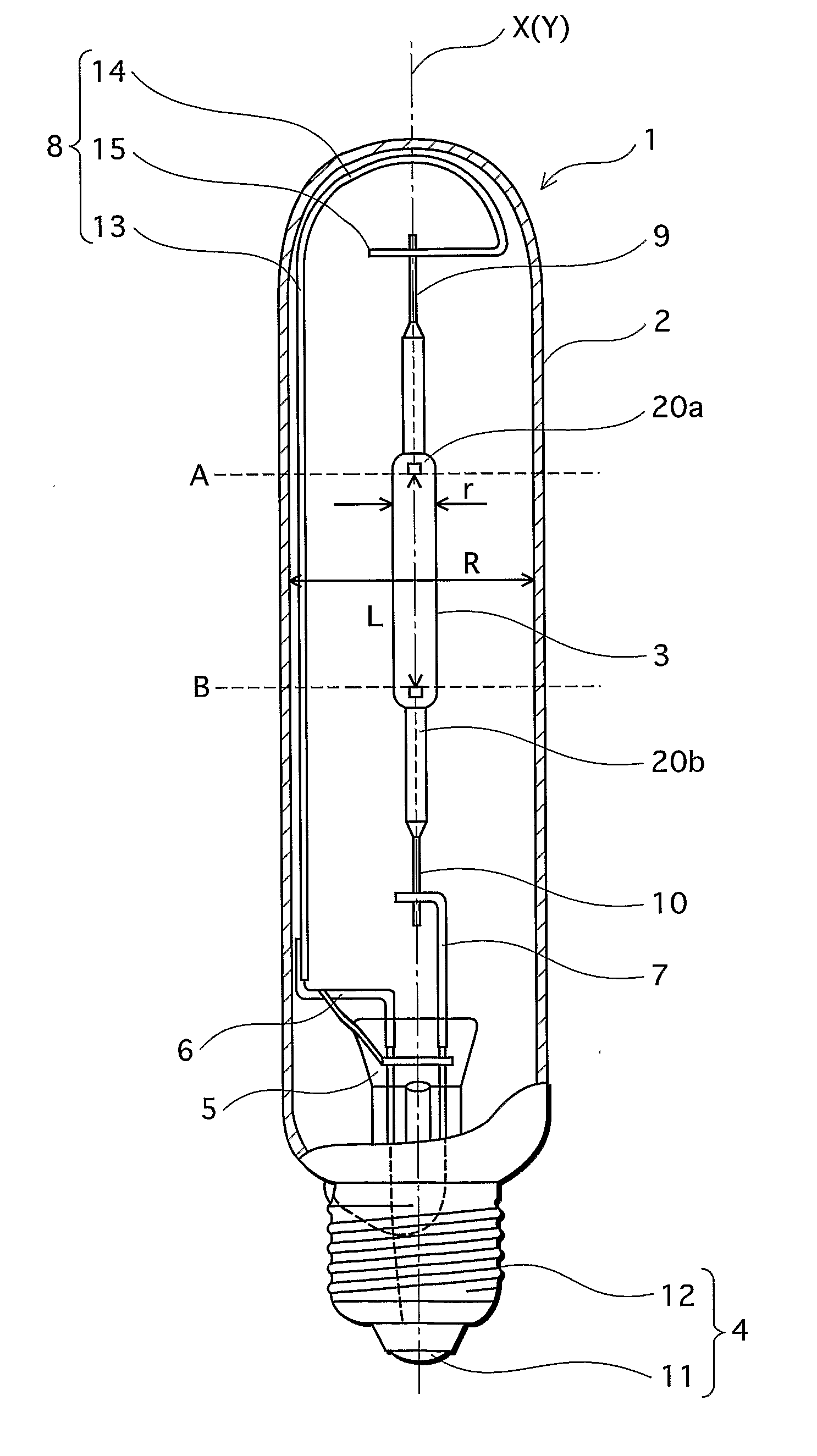
[0039]FIG. 1 shows a metal halide lamp (a ceramic metal halide lamp) 1 according to a first embodiment of the present invention. The metal halide lamp 1 with rated lamp wattage of 150 W has an overall length of 175 mm-185 mm (e.g. 180 mm). The metal halide lamp 1 comprises a casing tube 2, an arc tube 3, and a base 4. The casing tube 2 is an outer tube of the metal halide lamp 1, and the arc tube 3 is placed in the casing tube 2. The base 4 is a screw base (Edison screw base) fixed at an end of the casing tube 2. Note that the central axis (X in FIG. 1) in the longitudinal direction of the arc tube 3 substantially coincides with the central axis (Y in FIG. 1) in the longitudinal direction of the casing tube 2.

[0040] The casing tube 2 is a cylindrical tube made of, for example, hard glass or borosilicate glass. One end of the casing tube 2 is closed and round in shape, and the other end is closed by fixing thereto a flare 5 made of, for example, borosilicate glass...

second embodiment

2. Second Embodiment

[0091]FIG. 6 shows a metal halide lamp (a ceramic metal halide lamp) 28 according to a second embodiment of the present invention. Besides having two oxygen-releasing getters 29, the metal halide lamp 28 with rated lamp wattage of 150 W has the same configuration as the metal halide lamp 1, having rated lamp wattage of 150 W, of the first embodiment. The two oxygen-releasing getters 29 are attached onto the electric power supply wire 8, with one placed nearer the rounded closed end of the casing tube 2 and the other positioned nearer the flare 5.

[0092] Note that L / D is 8, and R / r is 3.0.

[0093] The constituent of the oxygen-releasing getters 29 is barium peroxide (BaO2). The oxygen-releasing getters 29 trap gas impurities in the casing tube 2 as well as release oxygen therein.

[0094] The pressure of the inside of the casing tube 2 was 1×10⁻¹ Pa at 300 K before the oxygen-releasing getters 29 released oxygen. After oxygen was released, the pressure increased to 1...

third embodiment

3. Third Embodiment

[0103]FIG. 8 shows a metal halide lamp 30 according to a third embodiment of the present invention. The metal halide lamp 30 with rated lamp wattage of 150 W has an overall length of 175 mm-185 mm (e.g. 180 mm). In addition to the configuration of the metal halide lamp 1, having rated lamp wattage of 150 W, of the first embodiment, the metal halide lamp 30 has a casing tube 31 and supporting members 32 that support the casing tube 31. The casing tube 31 made of a single-layered sleeve is placed between the outer tube 2 and the arc tube 3, surrounding the entire arc tube 3 (except for parts of the external lead wires 9 and 10 which are led to the outside of the arc tube 3).

[0104] As shown in FIG. 8, the arc tube 3, the outer body 2, and the casing tube 31 each have central axes, X, Y, and S, respectively, in the longitudinal direction. These central axes all substantially coincide with one another.

[0105] The outer body 2 is a cylindrical tube made of, for example...


PUM


Abstract

The present invention aims at providing a metal halide lamp that (i) prevents a decline in the lumen maintenance and a deterioration of quality in appearance due to the coloring of a casing tube surrounding the arc tube, and at the same time (ii) achieves high luminous efficiency. A metal halide lamp (1) has a pair of electrodes (20a&b) placed in an arc tube (3) made of translucent ceramic, and a sodium halide is enclosed therein. The metal halide lamp (1) satisfies L/D 4, where L (mm) is the length of the space between the electrodes (20a&b) and D (mm) is the internal diameter of the arc tube (3). The metal halide lamp (1) has a casing tube (2) surrounding the arc tube (3), at least around a portion between the electrodes (20a&b). Here, R/r 3.0 is satisfied, where R is the internal diameter of the casing tube (2) and r is the external diameter of the arc tube (3), within a region positionally corresponding to, in a radial direction of the arc tube, the space between the electrodes (20a&b), on a cross-sectional surface where an outer circumference of the arc tube (3) comes closest to the internal circumference of the casing tube (2).

Description

CROSS-REFERENCE TO RELATED APPLICATIONS [0001] This application is based on application No. 2003-424170 filed in Japan, the contents of which are hereby incorporated by reference. TECHNICAL FIELD [0002] The present invention relates to a metal halide lamp, and a luminaire using the same. BACKGROUND ART [0003] As to metal halide lamps used with luminaires for, for instance, outdoor lighting and high ceiling lighting, recent years an improvement in luminous efficiency has been strongly desired from the aspect of energy saving. [0004] In response to such a demand, a certain type of ceramic metal halide lamps has been proposed (see, e.g. Published Japanese translation of a PCT application No. 2000-501563). In a ceramic metal halide lamp of this type, translucent ceramic that withstands a high bulb wall loading, namely withstands use at a high temperature, is used as a material for the envelope of the arc tube. Such translucent ceramic is, for example, made of alumina. The arc tube has a...

Claims


Application Information

Patent Timeline
IPC IPC(8): H01J61/30H01J17/16F21S8/10F21Y101/00H01J61/34H01J61/82H01J61/88
CPCH01J61/827H01J61/34
Inventor KANAZAWA, YUKIYAUTSUBO, ATSUSHINOHARA, HIROSHIKAKISAKA, SHUNSUKENISHIURA, YOSHIHARU
Owner PANASONIC CORP
Why Eureka
Try Eureka