Method and system for counting particles in a laminar flow with an imaging device

a technology of imaging device and laminar flow, applied in the field of counting of imaged particles, to achieve the effect of optimizing accurate measurements, accurately determining particle densities, and reducing background nois

Active Publication Date: 2007-07-12
UNIVERSITY OF WYOMING
View PDF16 Cites 53 Cited by
  • Summary
  • Abstract
  • Description
  • Claims
  • Application Information

AI Technical Summary

Benefits of technology

[0056] The invention as described here is a novel integrated system, comprising imaging device, illuminator, flow channel, image processing means for reducing background and noise, counting means for counting particles, analysis means for correcting the counts to accurately determine particle densities, and control means for adjusting the system parameters to optimize accurate measurements in a short time interval.
[0057] Some embodiments of the present invention provide apparatus and methods for high throughput, high sensitivity detection and identification of samples in a translucent or transparent flowing liquid. This is accomplished by providing a relatively large cross section axial flow, in which cells or other target particles suspended in a liquid are observed as they flow through the focal plane of the imaging device. Measuring target particle density over a wide dynamic range of densities is accomplished by allowing for adjustment of operational parameters of the system in real-time based on a quick measurement of target particle density.
[0058] The present invention has the advantages of solid-phase cytometry (Lemarchand et al., Aquat. Microb. Ecol., 25: 301-309, 200), including detection of individual microorganisms, at a much lower cost (<$10,000). This invention is based on taxonomic identification using fluorescent dyes, including immunofluorescent dyes. The detection steps include:
[0062] A low-cost CCD (charge coupled device) or CMOS two-dimensional detector continuously images the flow channel so that it can image a flash of fluorescence emission each time a marked cell is illuminated by a laser diode or LED while passing through the focal plane of the detector.

Problems solved by technology

ing. Cell imaging and counting systems developed to date usually suffer from: 1.) high cost, 2.) unsatisfactory sensitivity, 3.) slowness, 4.) large size, 5.) insufficient spectral and / or spatial resolution, and / or 6.) labor-intensive prepara
Small diameter orifices are generally unworkable because they experience frequent clogging.
Historically, flow cytometers have been very large, expensive laboratory-based instruments.
They consume large amounts of power, and use complex electronics.
The size (desktop at the smallest), power requirements, and susceptibility to clogging (requiring operator intervention) of conventional flow cytometers precludes their use for many applications, such as field monitoring of water biocontamination.
U.S. Pat. No. 4,814,868 by James describes an imaging means for counting luminous particles in a boiler, but does not specifically apply to flow cytometry in general or Fountain Flow™ cytometry in particular, does not include a flow channel for entraining the particles, does not include an illumination device for exciting fluorescence in target particles, does not include a pumping mechanism, nor a way of controlling the pump rate, does not including a method for ensuring that particles are counted not more than once, does not provide for a means for counting measurements to be used to optimize system operational parameters on the fly, does not include a method for accurately counting particles by correcting counts for spatial confusion, does not include particle size as a counting criterion, and does not include the use of multiple counting algorithms based on particle density.
Although this invention does not suffer from the drawbacks listed above for alternative technologies, it is not suitable for applications where the flow medium is not transparent.

Method used


Image

  • Method and system for counting particles in a laminar flow with an imaging device
  • Method and system for counting particles in a laminar flow with an imaging device
  • Method and system for counting particles in a laminar flow with an imaging device

Examples


Embodiment Construction

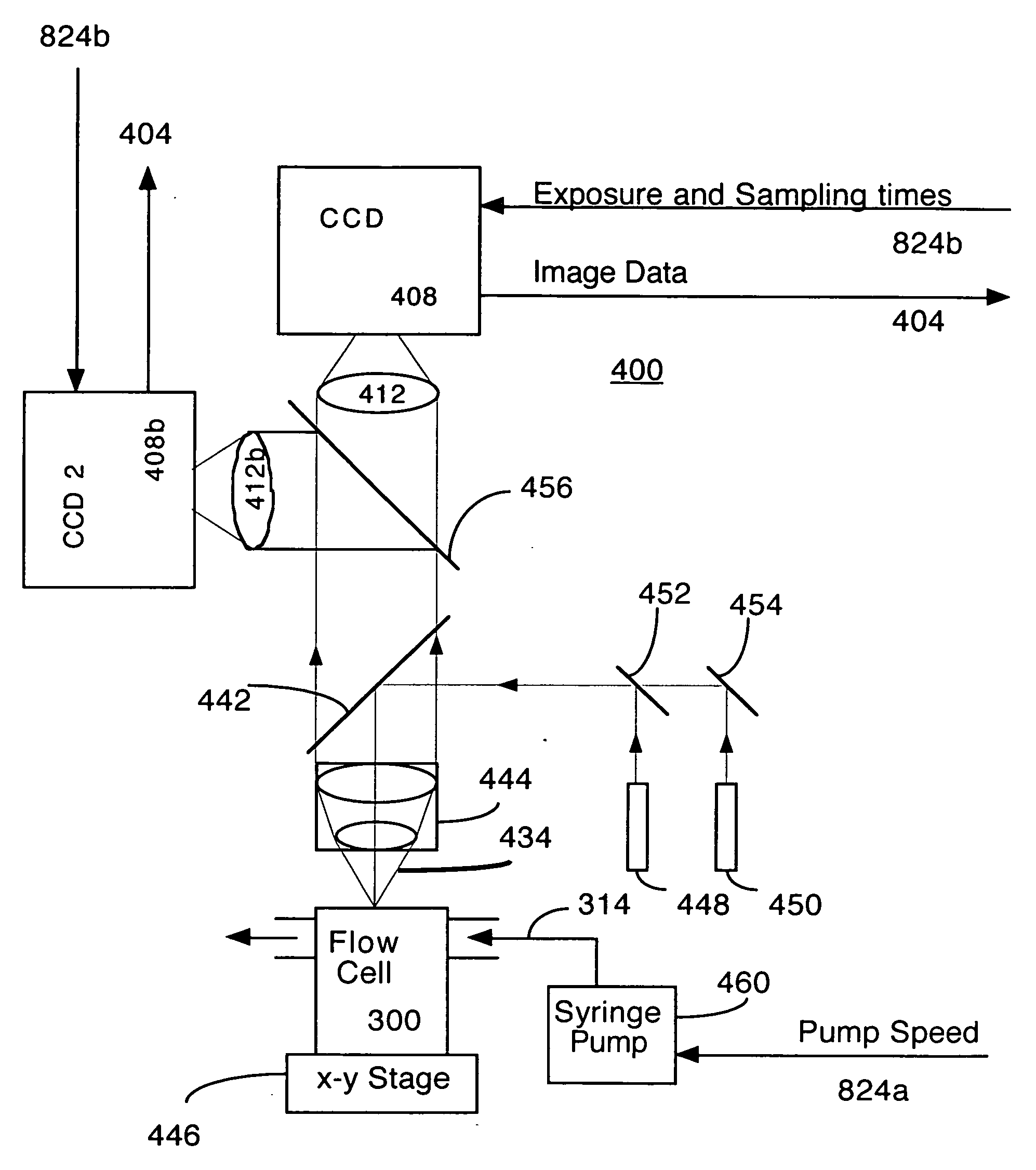
[0108] The present invention comprises apparatus and methods for counting particles in a flowing liquid. Both apparatus parameters and signal processing parameters are adjusted according to the concentration of particles in the flowing liquid.

[0109]FIGS. 3A and 3B are successive images from a Fountain Flow Cytometer according to the present invention. FIG. 3C shows the difference between the two images. FIG. 3C illustrates the kind of figure that might result from algorithm 808A (for low particle density) or 808B (for intermediate particle density), since sequential image differencing is used, as described below in conjunction with FIGS. 9 and 10.

[0110]FIGS. 4, 5, and 6 illustrate how particle detection varies according to the particle concentration in the flow. At lower concentrations, each particle may be counted, whereas at higher concentrations, the number of actual particles must be estimated from the lower number of detected particles.

[0111]FIG. 4 is a plot illustrating act...


PUM

PropertyMeasurementUnit
diameteraaaaaaaaaa
poweraaaaaaaaaa
imagingaaaaaaaaaa

Abstract

An invention is described which allows measurement of the concentration of fluorescent particles in a flowing (laminar) fluid by imaging the flow with a video camera. A beam of illumination is used to illuminate the target particles. Imaging optics are arranged to view the focal plane to form an image of the multiple fluorescent sample particles in the flow stream; a camera records the image formed by the imaging optics, and a counting algorithm enumerates the particles. Operational parameters of the system are adjusted according to an initial estimate of particle density, for example flow rate, exposure time, and sampling interval. In addition, the counting algorithm is selected according to the estimated particle density.

Description

BACKGROUND OF THE INVENTION [0001] 1. Field of the Invention [0002] The present invention relates to apparatus and methods for enumeration of specific target particles in a translucent or transparent flowing liquid. In particular, the present invention relates to counting of imaged particles wherein apparatus parameters and signal processing are adjusted according to estimated particle density in the flow. [0003] 2. Description of the Relevant Art Relevant U.S. Patents [0004] U.S. Pat. No. 4,814,868 March, 1989 James [0005] U.S. Pat. No. 5,978,435 November, 1999 Christensen et al. [0006] U.S. Pat. No. 6,115,119 September, 2000 Sieracki et al. [0007] U.S. Pat. No. 6,309,866 October, 2001 Ambrose et al. [0008] U.S. Pat. No. 6,710,879 March, 2004 Hansen et al. [0009] U.S. Pat. No. 6,731,100 May, 2004 Hansen et al. [0010] U.S. Pat. No. 6,765,656 July, 2004 Johnson [0011] Imaging and classification of low concentrations of selected target particles, cells in particular, in large volumes ...

Claims


Application Information

Patent Timeline
Patent Type & Authority Applications(United States)
IPC IPC(8): G06M11/02G01N15/02
CPCG01N15/1459G01N2015/1486G01N15/1463
Inventor JOHNSON, PAUL E.
Owner UNIVERSITY OF WYOMING
Why Eureka
Try Eureka