

Display device and method for inspecting the same
a technology for display devices and displays, applied in static indicating devices, emergency protective arrangements for limiting excess voltage/current, instruments, etc., can solve problems such as extended life and particularly susceptible organic layers to moistur
- Summary
- Abstract
- Description
- Claims
- Application Information
AI Technical Summary
Benefits of technology
Problems solved by technology
Method used
Image

Examples
embodiment mode 1
[0044] This embodiment mode explains a structure of a panel having a monitor light emitting element.
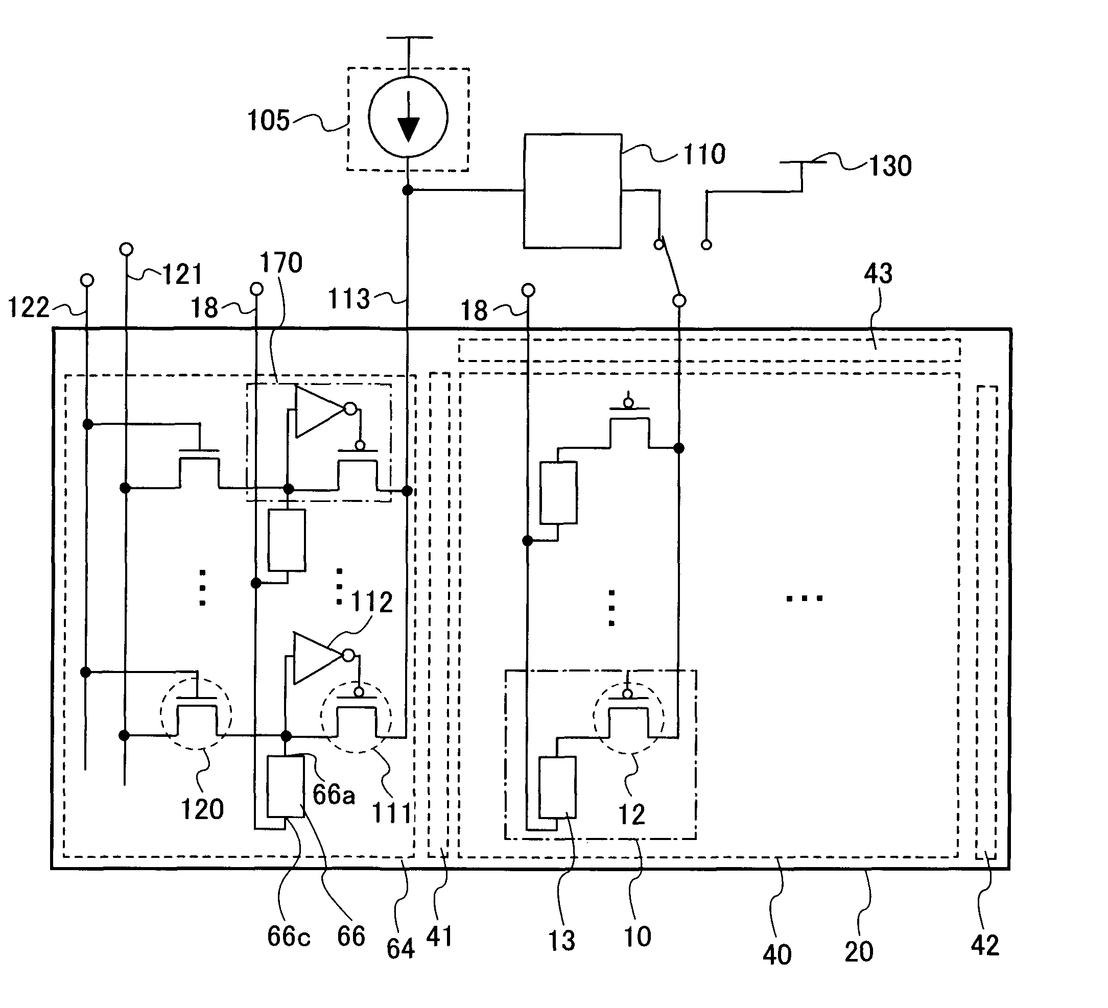
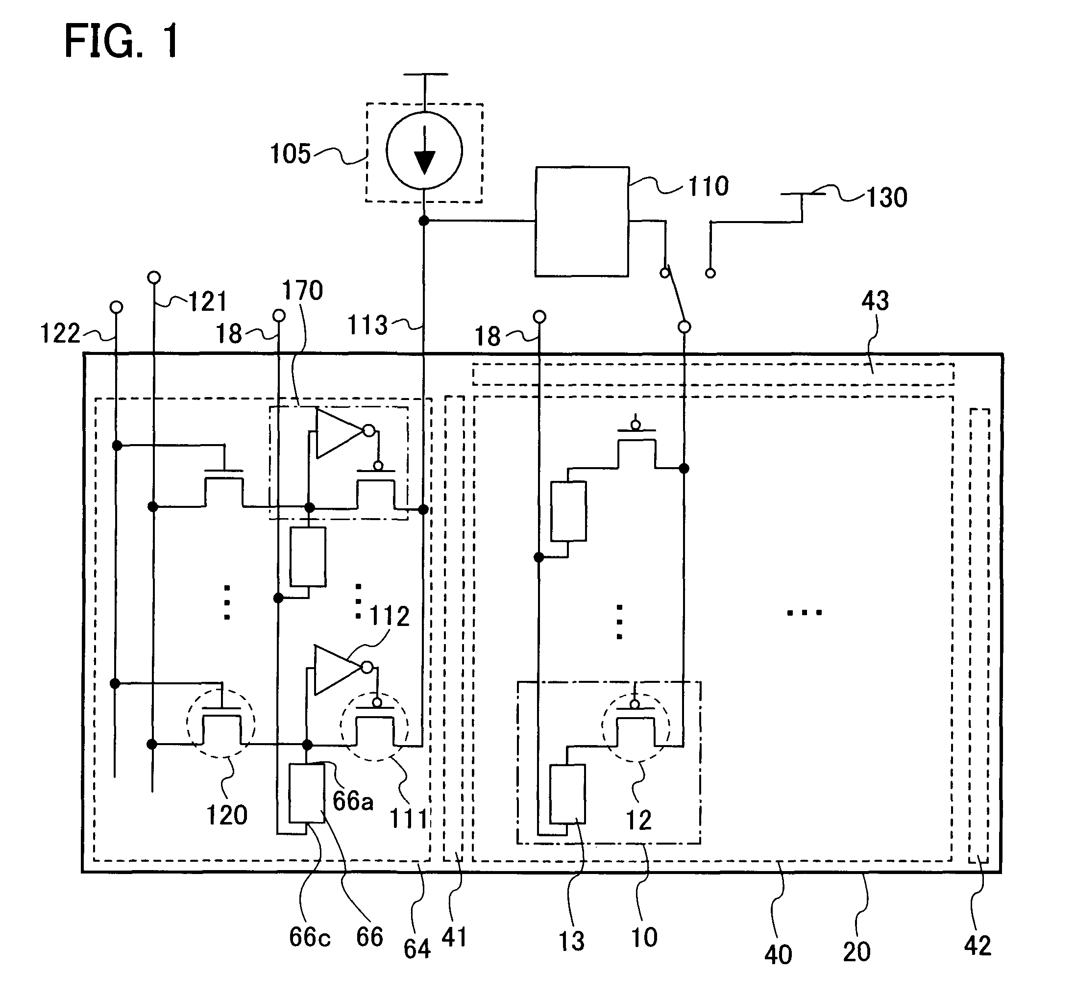
[0045] In FIG. 1, a pixel portion 40, a signal line driver circuit 43, a first scan line driver circuit 41, a second scan line driver circuit 42, and a monitor circuit 64 are provided over an insulating substrate 20.
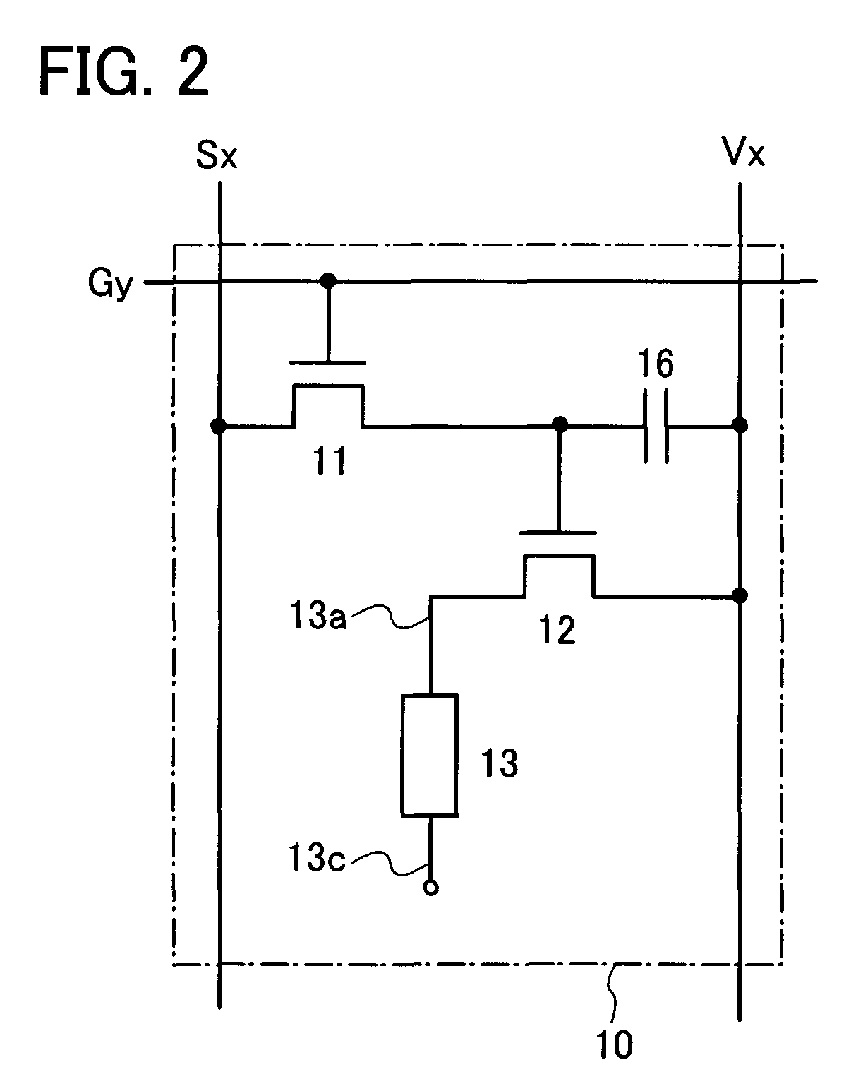
[0046] The pixel portion 40 is provided with a plurality of pixels 10. Each pixel is provided with a light emitting element 13 and a transistor which is connected to the light emitting element 13 and functions to control the supply of current (hereinafter referred to as a “driving transistor 12”). The light emitting element 13 is connected to a power supply line 18. Note that an example of a more specific structure of the pixel 10 is given in an embodiment mode below.
[0047] The monitor circuit 64 includes a monitor light emitting element 66, a transistor connected to the monitor light emitting element 66 (hereinafter referred to as a “monitor control transistor 111”), a...
embodiment mode 2
[0095] This embodiment mode explains in detail the operation of the monitor circuit 64 in Embodiment Mode 1, with reference to FIGS. 5A and 5B.
[0096] As shown in FIG. 5A, when an electrode with a high-level potential of electrodes of the monitor light emitting element 66 is the anode 66a and one with a low-level potential is the cathode 66c, the anode 66a is connected to an input terminal of the inverter 112, and the cathode 66c is connected to the power supply line 18, which is at a fixed potential. Therefore, when the anode and the cathode of the monitor light emitting element 66 are short-circuited, the potential of the anode 66a becomes close to the potential of the cathode 66c. As a result, the inverter 112 is supplied with a low potential which is close to the potential of the cathode 66c; therefore, a p-channel transistor 112p included in the inverter 112 is turned on. Then, the potential (Va_High) of the positive power supply terminal is outputted from the inverter 112, whi...
embodiment mode 3
[0106] This embodiment mode explains in detail an inspection method by which a defect in which the supply of a large amount of current to a short-circuited monitor light emitting element cannot be interrupted can be detected before shipment, with reference to FIGS. 6 to 7B.
[0107] First, in a state where the potential of the anode 66a of the monitor light emitting element 66 is equal to the potential of the cathode 66c, the potential of the positive power supply terminal of the inverter 112 is set to Va_Low as shown in FIG. 7A and a current is made to flow through the monitor line 113. The constant current flowing through the monitor line 113 at this time needs to be devised as described in Embodiment Mode 1. Specifically, a current, with which a potential when all of the current flowing through the monitor line 113 flows to one of the monitor light emitting elements 66 becomes lower than the potential Va_High when the potential supplied to the positive power supply terminal of the ...
PUM
 Abstract
Description
Claims
Application Information