High Performance Large Tolerance Heat Sink

a heat sink, large tolerance technology, applied in indirect heat exchangers, electrical generators, lighting and heating apparatuses, etc., can solve problems such as cost management, and achieve the effect of sufficient flexibility

Inactive Publication Date: 2007-07-12
LOCKHEED MARTIN CORP
View PDF52 Cites 47 Cited by
  • Summary
  • Abstract
  • Description
  • Claims
  • Application Information

AI Technical Summary

Benefits of technology

[0007] The convex foil construction may be adapted to maintain contact with a top surface of an electronic component mounted opposite the foil construction during variation in spacing between the heat sink and the electronic component. The convex foil construction may be sufficiently flexible to allow relative movement between the heat sink and the electronic component while maintaining a heat conduction path there between.
[0008] The foil construction may include two layers of foil sandwiching a layer of pyrolytic graphite there between. The foil construction may include one or more limited thermal vias between the two layers of foil.

Problems solved by technology

Driving constraints are interface thermal resistance, bulk thermal conductivity, machining tolerance range, contamination at the interface joints, electrical isolation, handling cost, and material cost.

Method used


Image

  • High Performance Large Tolerance Heat Sink
  • High Performance Large Tolerance Heat Sink
  • High Performance Large Tolerance Heat Sink

Examples


Embodiment Construction

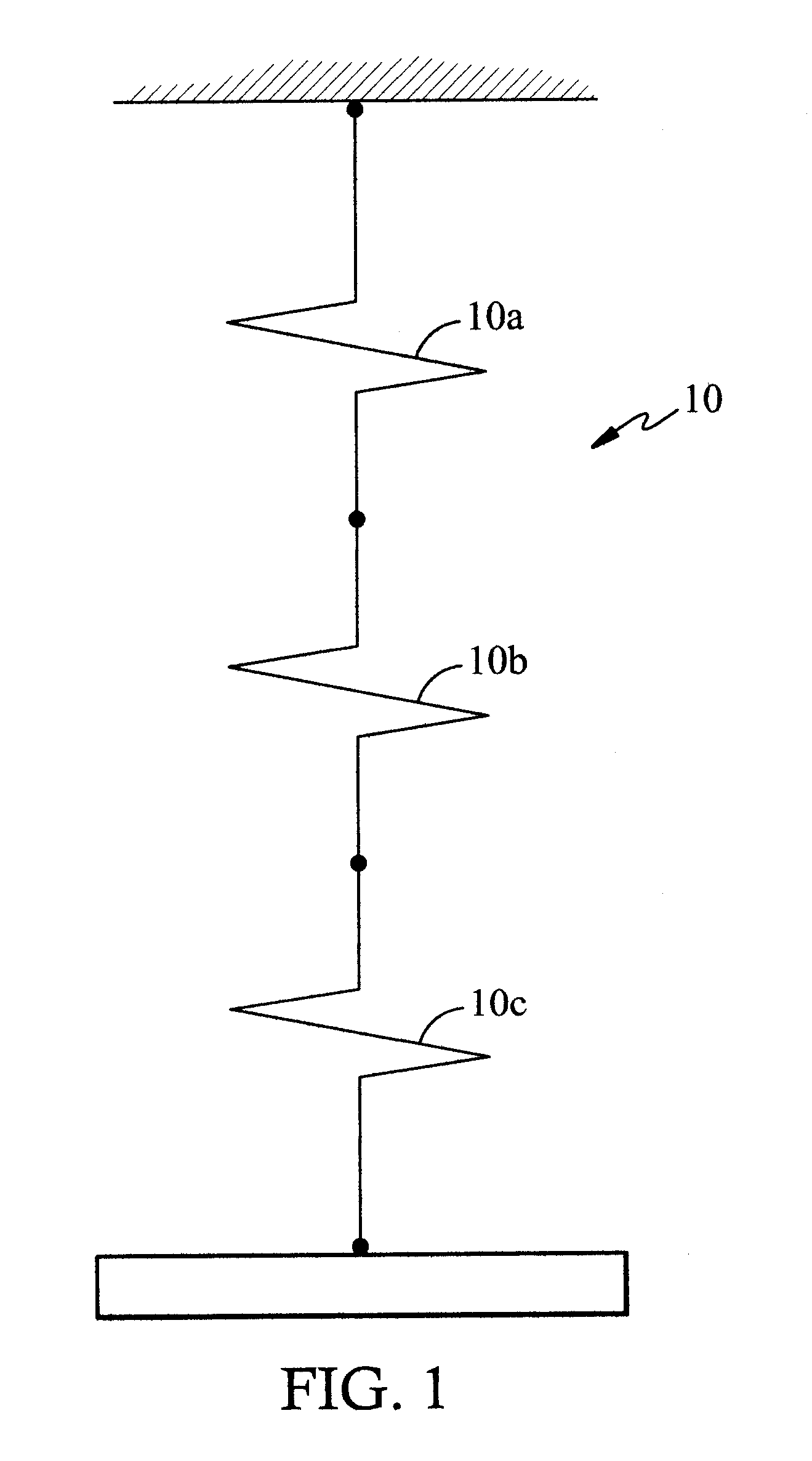
[0027] Conduction is defined as the transfer of heat through a static (non-moving) material. Heat will flow through the material if there is a temperature differential across it. The heat flow will be in the direction from the higher temperature to the lower temperature. The rate of heat flow will depend upon the temperature differential and the thermal conductivity (reciprocal of thermal resistance) of the material. The overall relationships are analogous to current flow in an electric circuit, where temperature differential is equivalent to voltage differential, thermal conductivity is equivalent to electrical conductivity, the rate of heat flow is equivalent to electric current, and thermal resistance is equivalent to electrical resistance.

[0028] An illustration of a thermal circuit 10 of a heat sink constructed in accordance with one embodiment of the present invention is shown in FIG. 1 and represented in equation form below:

Rth total=Rth bond 1(10a)+Rth thermal conductive mat...


PUM


Abstract

A heat sink apparatus for electronic components provides a heat sink and a deformable, convex foil construction affixed to the heat sink around a periphery of the foil construction and adapted to extend away from the heat sink to enable deformation of the convex foil construction as a result of contact with a top surface of an electronic component mounted opposite the foil construction.

Description

RELATED APPLICATIONS [0001] The present application claims priority from U.S. provisional patent application Ser. No. 60 / 757,750, filed Jan. 9, 2006.FIELD OF THE INVENTION [0002] This invention relates generally to heat sinks for electronic components, and more particularly, to heat sink / component interfaces that use heat conducting foil. BACKGROUND OF THE INVENTION [0003] Conduction is a heat transfer mechanism used in electronics design. Even if a system is designed for convection cooling of the circuit boards, conduction is still the dominant heat transfer mechanism for component devices located on circuit boards. This is especially true of power electronics, where concentrations of heat are developed in components. This heat must be transferred via conduction to the component case, the circuit board, or a heat sink before it can be handled by system level cooling mechanisms. Consequently, electronics designers are constantly evaluating new techniques of thermal conduction to dis...

Claims


Application Information

Patent Timeline
Patent Type & Authority Applications(United States)
IPC IPC(8): H05K7/20
CPCH01L23/373H01L23/433H01L2924/0002H01M8/0271H01M8/04089H01M8/04208H01M8/04216H01M8/04753H01M8/065H01M8/2465H01M8/2475H01M16/006H01M2250/30Y02E60/50Y02B90/18H01L2924/00H05K7/20445H05K7/20454H01L23/3672
Inventor DANDO, CHARLES H. IIILARCHEVEQUE, JONVOS, DAVID L.
Owner LOCKHEED MARTIN CORP
Why Eureka
Try Eureka