
Locking component for an embolic filter assembly

a technology of locking component and embolic filter, which is applied in the field of medical devices, can solve the problems of significant health problems of patients, particles that cannot be fully vaporized and entered the bloodstream, and emboli can be released into the circulatory system, and can be extremely dangerous and sometimes fatal to patients

Inactive Publication Date: 2007-07-12
ABBOTT CARDIOVASCULAR
View PDF99 Cites 79 Cited by
  • Summary
  • Abstract
  • Description
  • Claims
  • Application Information

AI Technical Summary

Benefits of technology

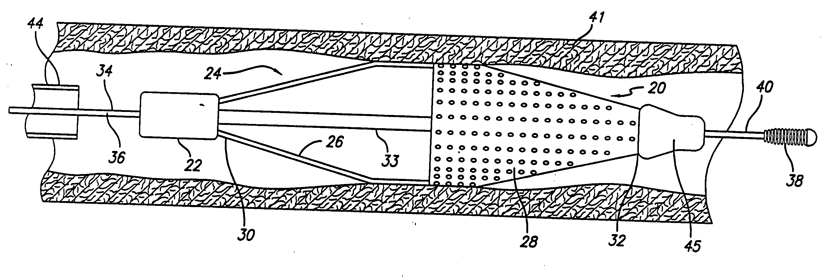
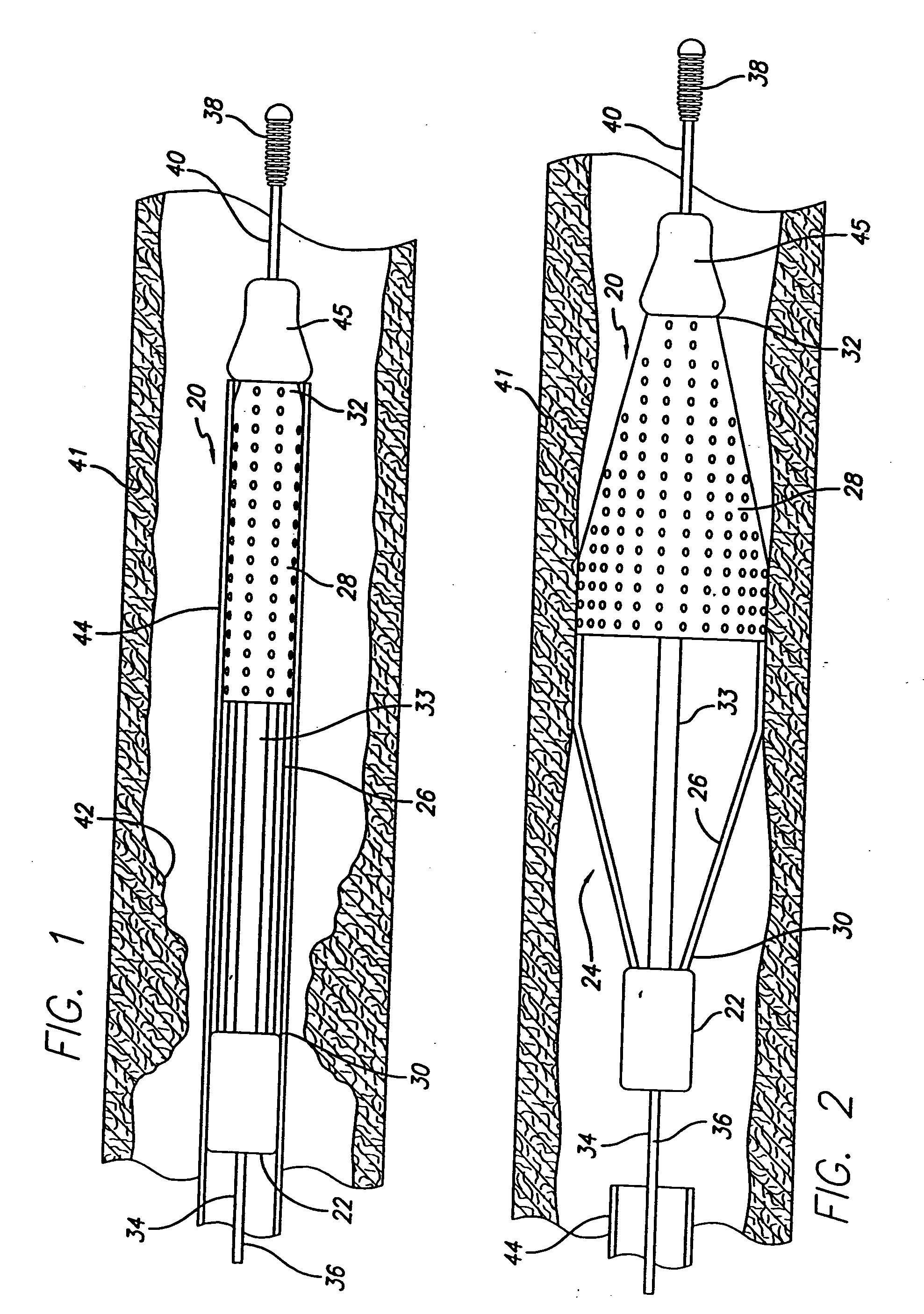
[0018] In another embodiment, an embolic protection system includes a guide wire having an elongated core without stops, and a filter assembly which is disposed on the elongated core for movement therealong. The filter assembly has a first end and a second end, and the locking component in this embodiment is a self-contracting elastic tube disposed on one of the ends of the filter assembly. One end of the elastic tube extends from the filter assembly while a free end of the elastic tube grips down around the wire core to secure the filter assembly thereon. When delivering the filter assembly to the distal end of the guide wire inside a body lumen, a hypotube is used to help move the filter assembly along the wire core. The hypotube is preferably positioned beneath the self-contracting elastic tube to prevent the elastic tube from gripping the guide wire while the filter assembly is traveling along the wire core; as such, the free end of the elastic tube is removably mounted onto the hypotube. By slightly withdrawing the hypotube from underneath, the free end of the elastic tube at least partially self-contracts and locks down onto the wire core.
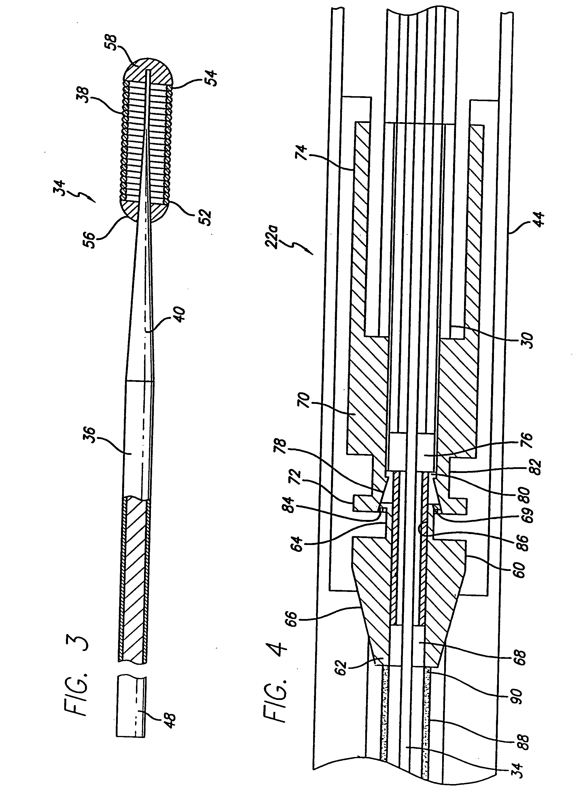
[0020] In order to control movement in opposite directions, it is possible to have a first locking device disposed at the first end of the filter assembly and a second locking device disposed at the second end of the filter assembly, where the first locking device prevents movement of the filter assembly in the distal direction and the second locking device prevents movement of the filter assembly in the proximal direction. In order to move the filter assembly along the guide wire distally toward the treatment site, the first locking device is temporarily disabled. To temporarily disable the first locking device, a hypotube engages the roller therein to prevent the roller from moving along the tapered interior diametrical profile and wedging itself against the housing and guide wire. Once the filter assembly is in position, the hypotube is withdrawn. The wedging action is thus enabled, and the first locking device prevents the filter assembly from moving farther distally.
[0025] If made from a metal, the material may be a nickel-titanium alloy having an austenitic shape set to a smaller diameter while the martensitic shape is deformed to have a larger diameter to facilitate movement along the guide wire. To activate the locking function, heat is introduced to the shrink tube so that the alloy transforms from martensite to its remembered austenitic shape. This causes the shrink down in diameter. Alternatively, the shrink tube may already be in the austenitic phase while in the body lumen, and a hypotube supporting the shrink tube from underneath prevents the shrink tube from shrinking. The hypotube is withdrawn at the appropriate instance thus allowing the shrink tube to constrict onto the guide wire.
[0027] The present invention further provides a separately deliverable filter assembly having an expandable basket or cage and a filter element. In use, the filter assembly is designed to capture embolic debris created during the performance of a therapeutic interventional procedure or other unwanted particulates entrained in the fluid of a body vessel. The present invention allows the physician to deliver the guide wire of his or her choice with “front line” capabilities to steer through the tortuous anatomy, while still being able to provide filtering protection in the form of a separately deliverable attachment.

Problems solved by technology

However, there is one common problem which can become associated with all of these non-surgical procedures, namely, the potential release of embolic debris into the bloodstream that can occlude distal vasculature and cause significant health problems to the patient.
Additionally, while complete vaporization of plaque is the intended goal during laser angioplasty, sometimes particles are not fully vaporized and enter the bloodstream.
When any of the above described procedures are performed in the carotid arteries, the release of emboli into the circulatory system can be extremely dangerous and sometimes fatal to the patient.
Debris carried by the bloodstream to distal vessels of the brain can cause cerebral vessels to occlude, resulting in a stroke, and in some cases, death.
Therefore, although cerebral percutaneous transluminal angioplasty has been performed in the past, the number of procedures performed has been somewhat limited due to the justifiable fear of an embolic stroke occurring should embolic debris enter the bloodstream and block vital downstream blood passages.
However, it is often difficult to control the size of the fragments which are formed, and the potential risk of vessel occlusion still exists, making such a procedure in the carotid arteries a high risk proposition.
However, as mentioned above, there can be complications associated with such systems if the catheter does not remove all of the embolic material from the bloodstream.
Also, a powerful suction could cause trauma to the patient's vasculature.
While a filter can be effective in capturing embolic material, the filter still needs to be collapsed and removed from the vessel.
During this step, there is a possibility that trapped embolic debris can backflow through the inlet opening of the filter and enter the bloodstream as the filtering system is being collapsed and removed from the patient.
The bulk and location of the stop on the guide wire, however, can detrimentally affect the ability of the physician to steer the guide wire and to reach the target area in the patient's vasculature.
Depending on its shape and size, the stop formed on the guide wire might cause the guide wire to hang or catch inside a patient's tortuous anatomy, or it might injure the vessel wall.
Accordingly, the presence of the stop near the distal end of the guide wire may cause unwanted problems during advancement of the guide wire through the patient's vasculature.
If the filter device requires a specially designed guide wire having a unique fitting or stop to lock to that filter device, then the physician cannot use his or her preferred guide wire due to possible incompatibility between the favored guide wire and the filter device.

Method used


Image

  • Locking component for an embolic filter assembly
  • Locking component for an embolic filter assembly
  • Locking component for an embolic filter assembly

Examples


Embodiment Construction

[0051] The present invention relates to a locking component used to lock a medical device on to a standard guide wire. As such, the locking component does not need to be used with a specially designed guide wire having a complementary “fitting” or “stop” thereon in order to accomplish the locking function. That is, such a standard guide wire has no “fitting” or “stop” defined as any structure formed on the wire or attached thereto before sterilization, whose position relative to the wire is generally stationary or has very restricted linear and / or rotational movement, that is intended to engage a mating locking component of a filtering device or like medical device in order to (a) prevent or limit the movement of that filter device along the guide wire, and / or to (b) assist in the deployment of the filter device.

[0052] The above definition of a “fitting” or “stop,” however, does not encompass common fixtures found on a guide wire core such as a tip coil, a shaping ribbon, or the li...


PUM


Abstract

A locking component for locking a medical device onto a guide wire. Such medical devices include, for example, an embolic filter assembly used to capture embolic material that may be created and released into a patient's vasculature during a stenting or angioplasty procedure. The embolic filter assembly tracks along the guide wire, and is delivered to a treatment site where it is locked in place and deployed. The locking component enables the filter assembly to lock onto any standard guide wire, and does not require a modified guide wire that has a specially-designed fitting or stop to accomplish the locking function.

Description

BACKGROUND OF THE INVENTION [0001] The present invention relates generally to medical devices used to perform interventional procedures in a patient's vasculature, which can be delivered through a body lumen via a steerable guide wire and into an area of treatment such as, for example, a stenosed or occluded region of an artery or other body vessel. The present invention is more particularly directed to a locking component disposed on a medical device to allow the medical device to be delivered along the guide wire to the treatment area and locked in place. The locking component of the present invention is intended for use on a standard guide wire of the physician's choice, and does not require a modified guide wire with specially-designed stops or other mechanisms to accomplish the locking function. [0002] Numerous medical procedures have been devised for treating occluded blood vessels to allow blood to flow without obstruction. Such procedures usually involve the percutaneous int...

Claims


Application Information

Patent Timeline
IPC IPC(8): A61M29/00
CPCA61F2/01A61F2002/011A61F2230/0067A61F2002/018A61F2230/0006A61F2002/015A61F2/011
Inventor BURKETT, DAVID H.ESSELSTEIN, ROBERT C.LIND, KATHERN J.BUAN, PABLITOHAZELDEN, ROBERT C.TOKARCHIK, THOMAS IIIGRANDFIELD, RYANBALDWIN, AARONCORNISH, WAYNE E.YIP, PHILIP S.
Owner ABBOTT CARDIOVASCULAR
Learn More