Al technical title is built by PatSnap Al team. It summarizes the technical point description of the patent document.
a navigation system and vehicle technology, applied in the direction of navigation instruments, identification means, instruments, etc., can solve the problem that the map display is currently one of the largest cost factors of the vehicle navigational system
Inactive Publication Date: 2007-07-12
DONNELLY CORP
View PDF99 Cites 70 Cited by
Summary
Abstract
Description
Claims
Application Information
AI Technical Summary
This helps you quickly interpret patents by identifying the three key elements:
Problems solved by technology
Method used
Benefits of technology
[0005] One aspect of the present invention offers a complete GPS system, including antenna, receiver and a GPS information display into a vehicular mirror assembly, and particularly an interior rearview mirror assembly. Provision of such a mirror-mounted GPS system as a unitary, complete assembly has several advantages, including obviating an automaker from having to specifically design a dashboard or other interior cabin spaces and would decrease the time to market associated with such level of feature integration. Also, provision of a mirror-mounted GPS system as a unitary, complete assembly facilitates supply of such assemblies as retrofits and as aftermarket installations, and generally increases an automaker's ability to offer a GPS feature as an option on selected vehicles.
[0006] A particular advantage from locating the information display of a GPS system at the interior rearview mirror assembly in the interior vehicular cabin is that such a mirror-mounted GPS display can facilitate multi-tasking by the driver. Thus, there is a need to intelligently filter mapping information to provide useful, but usable, data to the driver. A further object of this present invention is to economically provide a driver-usable GPS display. Map displays are currently one of the largest cost factors in vehicle navigational systems. Thus, it would be desirable to avoid or reduce this cost by providing a simpler means of display to the driver.
[0007] Another aspect of this invention is the location of the GPS antenna and the receiver in the exterior side view assembly. A further aspect is the processing by that exterior side view mirror receiver of GPS location data received by the antenna and fed from there to the receiver, providing an output from that location, that is external to the vehicle cabin, into the vehicle cabin. This has the advantage of the optimal field of view for the antenna for communication to GPS satellites. The placement of the receiver in an exterior side view mirror assembly in close proximity to the antenna also is preferred to avoid RFI and EMC issues associated with low level RF signals. Locating the GPS antenna at a distance from the GPS receiver may render the GPS system subject to stray RF noise from cellular phones and high power portable transmitters, such as CB's and handheld radios.
Problems solved by technology
Map displays are currently one of the largest cost factors in vehicle navigational systems.
Method used
Image
Click on the blue label to locate the original text in one second.
Reading with bidirectional positioning of images and text.
Examples
Embodiment Construction
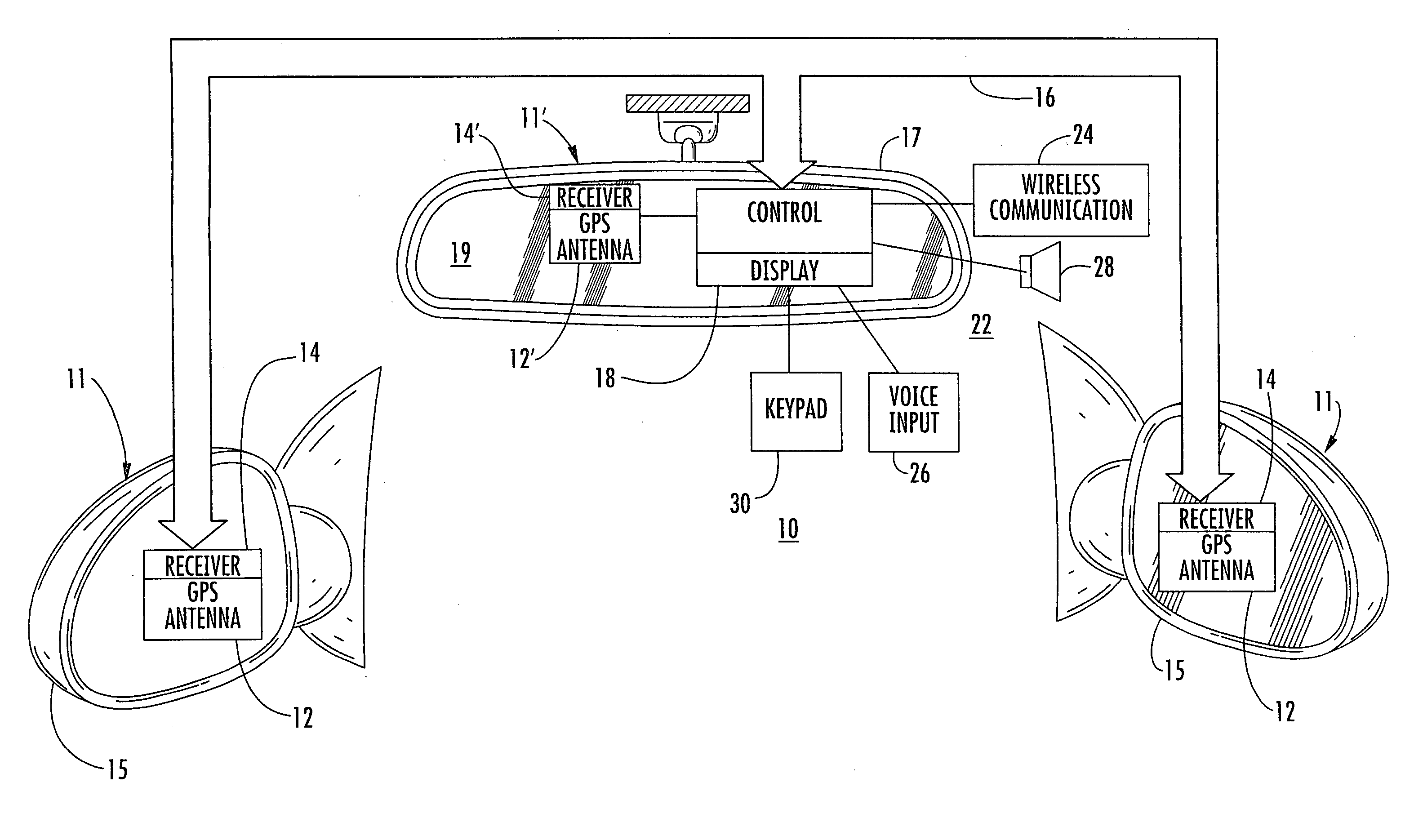
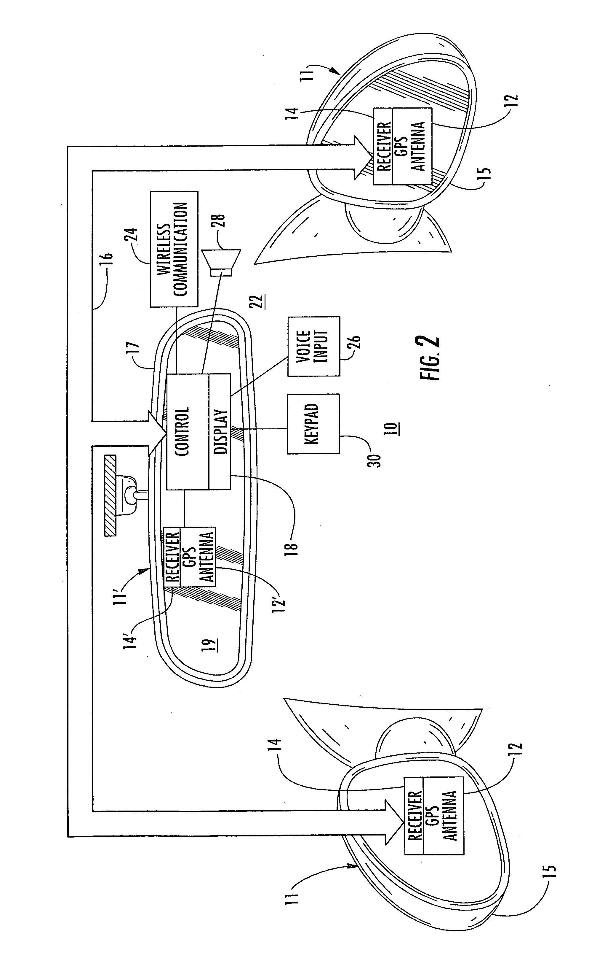
[0010] Referring now to the drawings and the illustrated embodiments depicted therein, a vehicular rearview mirror-based navigation system 10, in a preferred embodiment of the present invention, includes one or more GPS receiving systems 11 exterior mirror-mounted antennas 12 that receive location information form GPS satellites. A GPS receiver 14, to which is connected the GPS antenna 12, may also be mounted within an exterior side view mirror assembly 15. The geographic data output from the GPS receiver 14 is then transferred to an interior rearview mirror assembly 17 for display with the driver via a communication channel 16 such as by a wire connection, a vehicle data bus connection such as a LIN (Local Interconnet Network) or a CAN bus, as known in the art, or wirelessly such as via short-range RF data transmission using a protocol such as the BLUETOOTH protocol such as is available from Motorola of Schaumberg, Ill. Alternatively, a GPS receiving system 11 including an interior...
PUM
Abstract
An interior rearview mirror system for a vehicle includes an interior rearview mirror assembly having a reflective element. An information display is at the interior rearview mirror assembly and displays information for viewing by a driver of the vehicle. The information display may be located behind the reflective element and viewable through the reflective element by the driver of the vehicle. The mirror system includes a handheld device having a position locator and being capable of establishing a geographical position of the handheld device. The information displayed by the information display is derived at least in part via a wireless communication link with the handheld device. The information display may include a display of turn-by-turn information for viewing by the driver of the vehicle. The information display may comprise a video screen.
Description
CROSS-REFERENCE TO RELATED APPLICATIONS [0001] This application is a continuation of U.S. patent application Ser. No. 10 / 755,627, filed Jan. 12, 2004 (Attorney Docket DON01 P-1136), which is a continuation of U.S. patent application Ser. No. 10 / 287,178, filed on Nov. 4, 2002, now U.S. Pat. No. 6,678,614, which is a continuation of patent application Ser. No. 09 / 799,414, filed on Mar. 5, 2001, now U.S. Pat. No. 6,477,464, which claims priority from U.S. provisional application Ser. No. 60 / 187,960, filed on Mar. 9, 2000, the disclosures of which are hereby incorporated herein by reference in their entireties, and application Ser. No. 10 / 755,627 is a continuation-in-part of U.S. patent application Ser. No. 09 / 449,121, filed on Nov. 24, 1999, now U.S. Pat. No. 6,428,172 B1.BACKGROUND OF THE INVENTION [0002] Vehicle-based global-positioning systems (GPS) are capable of providing complete mapping information, including street layout, street names, directions, landmarks, addresses, and the...
Claims
Application Information
Patent Timeline
Application Date:The date an application was filed.
Publication Date:The date a patent or application was officially published.
First Publication Date:The earliest publication date of a patent with the same application number.
Issue Date:Publication date of the patent grant document.
PCT Entry Date:The Entry date of PCT National Phase.
Estimated Expiry Date:The statutory expiry date of a patent right according to the Patent Law, and it is the longest term of protection that the patent right can achieve without the termination of the patent right due to other reasons(Term extension factor has been taken into account ).
Invalid Date:Actual expiry date is based on effective date or publication date of legal transaction data of invalid patent.
Patent Type & Authority Applications(United States)