Heat exchanger and refrigerant passage portion connecting structure for refrigeration cycle

a technology of refrigerant passage and connecting structure, which is applied in the field of heat exchangers, can solve the problems of rainwater or the like ingressing into the interstice, and achieve the effects of easy shifting, high corrosion resistance, and smooth installation

Active Publication Date: 2007-07-19
MAHLE INT GMBH
View PDF8 Cites 7 Cited by
  • Summary
  • Abstract
  • Description
  • Claims
  • Application Information

AI Technical Summary

Benefits of technology

[0035] With the heat exchanger according to par. 1), the liquid receiver is fixed to the connecting block with the contact faces of the fixing portions of the block and receiver in intimate contact with each other, and the seal member is liquid-tightly provided around respective outer peripheral surfaces of both the fixing portions so as to cover a boundary between the contact faces of the fixing portions of the block and the receiver. Rainwater or the like can therefore be prevented from ingressing into an interstice between the contact face of the block fixing portion and the contact face of the receiver fixing portion by the function of the seal member. This precludes corrosion from developing in the contact faces.
[0052] The process of par. 24) for fabricating a refrigerant passage portion connecting structure includes applying a volatile lubricant to the outer peripheral surface of a fixing portion of at least one of two blocks, thereafter fitting a tubular seal member around the outer peripheral surface of the fixing portion having the lubricant applied thereto, subsequently fastening the two blocks together with contact faces of the fixing portions of the blocks in intimate contact with each other, and thereafter shifting the tubular seal member to place the tubular seal member around both the fixing portions so as to cover a boundary between the contact faces of the fixing portions. The tubular seal member can therefore be shifted easily by the action of the volatile lubricant and installed in place smoothly. Since the lubricant vaporizes after the installation of the seal member, the seal member will not easily shift after the vaporization of the lubricant.

Problems solved by technology

With the unit-type heat exchanger disclosed in the above publication, however, it is likely that rainwater or the like will ingress into an interstice between the contact faces of the block and the liquid receiver.
However, with such a refrigerant passage portion connecting structure, rainwater or the like is likely to penetrate into an interstice between the contact faces of the two blocks.

Method used


Image

  • Heat exchanger and refrigerant passage portion connecting structure for refrigeration cycle
  • Heat exchanger and refrigerant passage portion connecting structure for refrigeration cycle
  • Heat exchanger and refrigerant passage portion connecting structure for refrigeration cycle

Examples


embodiment 1

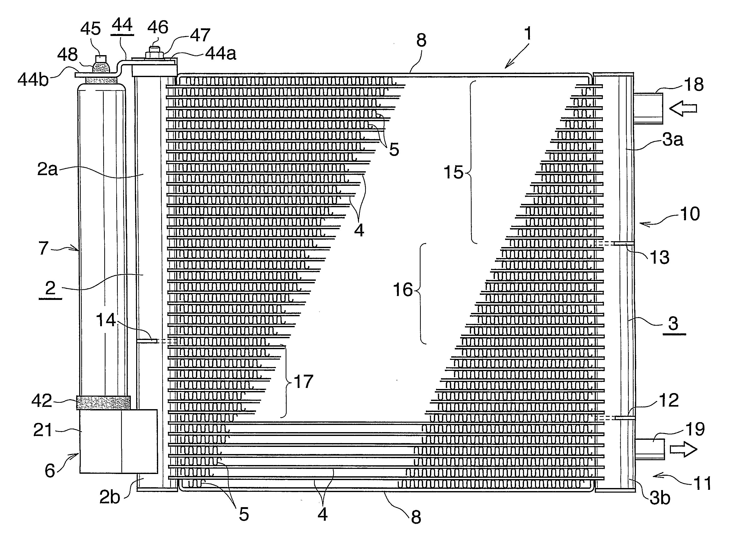
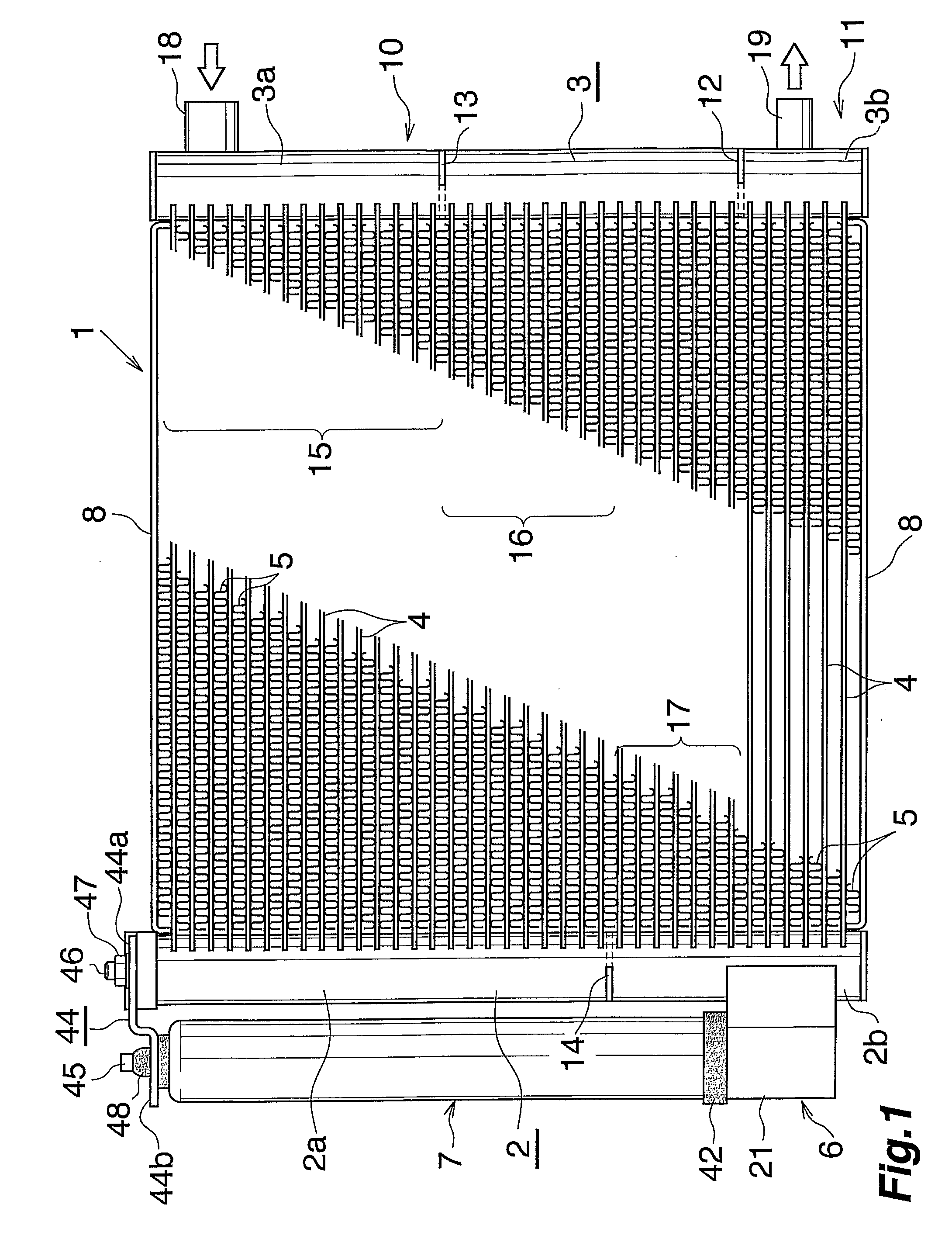
[0063] This embodiment is shown in FIGS. 1 to 4 and is a unit-type heat exchanger according to the invention and comprising a condenser portion having the function of a condenser and a supercooler portion having the function of a supercooler which are in the form of a unit.

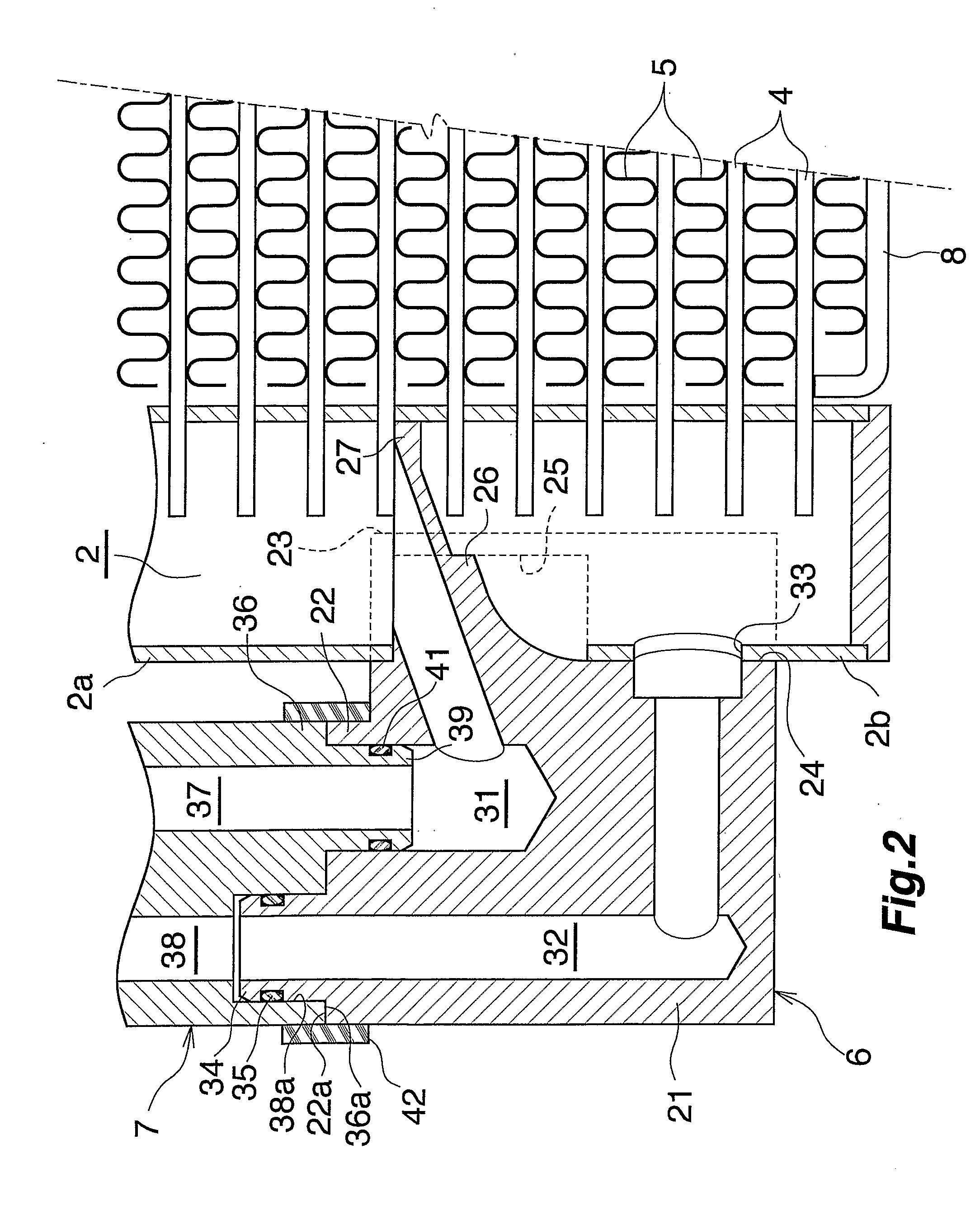
[0064]FIG. 1 shows the overall construction of the heat exchanger of the unit type, and FIGS. 2 and 3 show the constructions of the main portions thereof. FIG. 4 shows some steps of a process for fabricating the unit-type heat exchanger.

[0065] With reference to FIG. 1, the heat exchanger 1 comprises a pair of left and right aluminum headers 2, 3 extending upward or downward and spaced apart from each other, a plurality of aluminum refrigerant tubes 4 arranged between the headers 2, 3 in parallel upward or downward at a spacing and joined at opposite ends to the headers 2, 3 by brazing, corrugated aluminum fins 5 arranged between and brazed to respective adjacent pairs of refrigerant tubes 4, a receiver connectin...

embodiment 2

[0089] The present invention is embodied as a structure for connecting pipes for use in a piping system for passing a refrigerant therethrough in a refrigeration cycle. This embodiment is shown in FIG. 6.

[0090] With reference to FIG. 6, the pipe connecting structure 50 comprises a first block 52 made of a metal, i.e., aluminum and fixed to an end of a first pipe 51 made of a metal, i.e., aluminum, and a second block 54 made of a metal, i.e., aluminum and fixed to an end of a second pipe 53 made of a metal, i.e., aluminum.

[0091] The first block 52 comprises a block body 55 and a fixing portion 56 formed at the left end of the block body 55 integrally therewith. With this embodiment, the block body 55 and the fixing portion 56 have the same shape and the same size in contour and are in the form of a vertically elongated oblong when seen from one side although not shown. The fixing portion 56 has a left side face serving as a flat intimate contact face 56a. The fixing portion 56 has ...

embodiment 3

[0100] The present invention is embodied as a structure 70 for connecting pipes for use in a piping system for passing a refrigerant therethrough in a refrigeration cycle. This embodiment is shown in FIG. 7.

[0101] In the case of the pipe connecting structure 70 of this embodiment, a first block 52 is secured to both the forward ends of two first pipes 51, and a second block 54 is secured to both the forward ends of two second pipes 53. The structure 70 has the same construction as the pipe connecting structure 50 of Embodiment 2 described with the exception of the following features. The blocks 52, 54 have two channels 57 and two channels 62, respectively. The ends of the pipes 51, 53 are inserted into respective large-diameter portions 57a, 62a of the channels 57, 62 and secured to the corresponding blocks 52, 54 by welding. A male pipe portion 63 projecting rightward and to be inserted into a second large-diameter portion 57b of each channel 57 of the first block 52 is formed aro...


PUM


Abstract

Fixed to the peripheral wall of a header 2 of a unit-type heat exchanger 1 is a receiver connecting block 6 having channels 31, 32 for causing the interior of the header 2 to communicate with the interior of a liquid receiver 7 therethrough. The block 6 and the liquid receiver 7 have respective fixing portions 32, 36 and respective contact faces 22a, 36a each provided on the fixing portion. The outer peripheral surfaces of the fixing portions 22, 36 have respective contours of the same shape and the same size. The liquid receiver 7 is fixed to the block 6 with the contact faces 22a, 36a of the fixing portions 22, 36 in intimate contact with each other. A tubular seal member 42 having rubber elasticity is liquid-tightly fitted around the fixing portions 22, 36. The seal member 42 has an inner shape smaller than the contours of the outer peripheral surfaces of the fixing portions 22, 36 and is fitted as elastically deformed around the fixing portions 22, 36. Rainwater or the like can be prevented from ingressing into an interstice between the contact faces of the block and the liquid receiver.

Description

CROSS REFERENCE TO RELATED APPLICATION [0001] This application is an application filed under 35 U.S.C. §111(a) claiming the benefit pursuant to 35 U.S.C. §119(e) (1) of the filing date of Provisional Application No. 60 / 570,475, filed May 13, 2004 pursuant to 35 U.S.C. §111(b).TECHNICAL FIELD [0002] The present invention relates to heat exchangers for use in refrigeration cycles providing, for example, motor vehicle air conditioners, and structures for connecting refrigerant passage portions in refrigeration cycles. [0003] The upper and lower sides of FIG. 1 will be referred to herein and in the appended claims as “upper” and “lower.”BACKGROUND ART [0004] The combination of a header and a liquid receiver fixed thereto has been placed into use as a condenser in refrigeration cycles providing motor vehicle air conditioners so as to render the condenser easier to install in vehicle bodies and to reduce the installation space. Also placed into use are supercoolers for supercooling the li...

Claims


Application Information

Patent Timeline
Patent Type & Authority Applications(United States)
IPC IPC(8): F28B1/00F16J15/06F25B39/00F25B39/04F25B40/02F25D17/02F28F9/02F28F9/04
CPCF25B39/04F25B40/02F25B2339/044F25B2339/0442F25B2339/0446F28F9/0256F28D1/05375F28D2021/0084F28F9/0246F28F9/0253F25B2500/01
Inventor SENO, YOSHIHIKOKAMOSHIDA, OSAMUYASUTAKE, TAKAYUKI
Owner MAHLE INT GMBH
Why Eureka
Try Eureka