High-frequency filter

a filter and high-frequency technology, applied in waveguides, basic electric elements, waveguide type devices, etc., can solve the problems of reducing broadband performance, signal receiving error at user end, and quality degradation, and achieve low insertion loss, improve wireless communication signal receiving quality, and high selectivity

Inactive Publication Date: 2007-07-19
PRIME ELECTRONICS & STATELLITCS
View PDF9 Cites 11 Cited by
  • Summary
  • Abstract
  • Description
  • Claims
  • Application Information

AI Technical Summary

Benefits of technology

[0007]The present invention has been accomplished under the circumstances in view. It is the main object of the present invention to provide a high-frequency filter, which has high selectivity and low insertion loss, improves wireless communication signal receiving quality, increases product yield, and lowers manufacturing cost.

Problems solved by technology

An excessive intensity of image signal degrades the quality of wanted signal, and may result in a signal receiving error at the user end.
However, this measure requires an additional component parts installation space and may sacrifice bandwidth and gain of pass band, lowering broadband performance.
More particularly, in a modern microwave communication system, C-band and Ku-band are insufficient to meet the demand thus the higher Ka-band is provided.
The design of increasing the order of the filter under the condition of rising the radio frequency and local oscillating frequency and increasing the bandwidth without changing the intermediate frequency is insufficient to deal with the demand.
However, the transmission lines that are arranged together in a high density manner tend to be affected by PCB (Printed Circuit Board) manufacturing defects, such as miss-alignment of photo mask or etching error of conducting lines.
When these manufacturing problems mentioned above do exist, either need a re-simulation design that will waste much manufacturing time and increase manufacturing cost, or may cause a minor shift of the resonance frequency of the filter, thereby lowering product yield.
These situations result in the problem of signal quality deterioration or signal receiving error at the user end.

Method used


Image

  • High-frequency filter
  • High-frequency filter
  • High-frequency filter

Examples


first embodiment

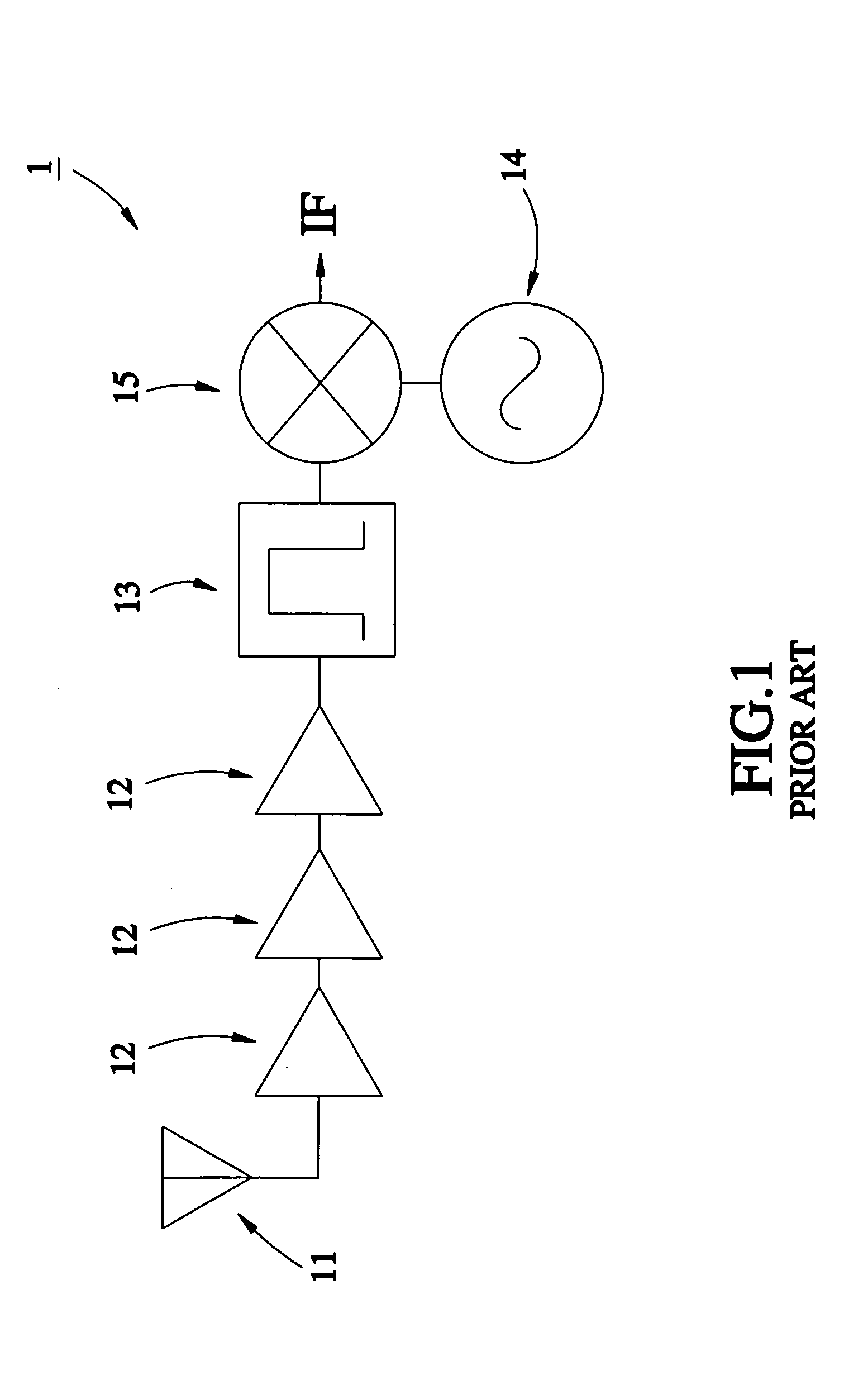
[0014]Referring to FIGS. 2 and 3, a high-frequency filter 2 in accordance with the present invention can be utilized as an image rejection filter for LNB (Low Noise Block) Down Converter. The high-frequency filter 2 comprises a printed circuit 20 on a printed circuit board (not shown), and a tuner 30 at the top side of the printed circuit 20.

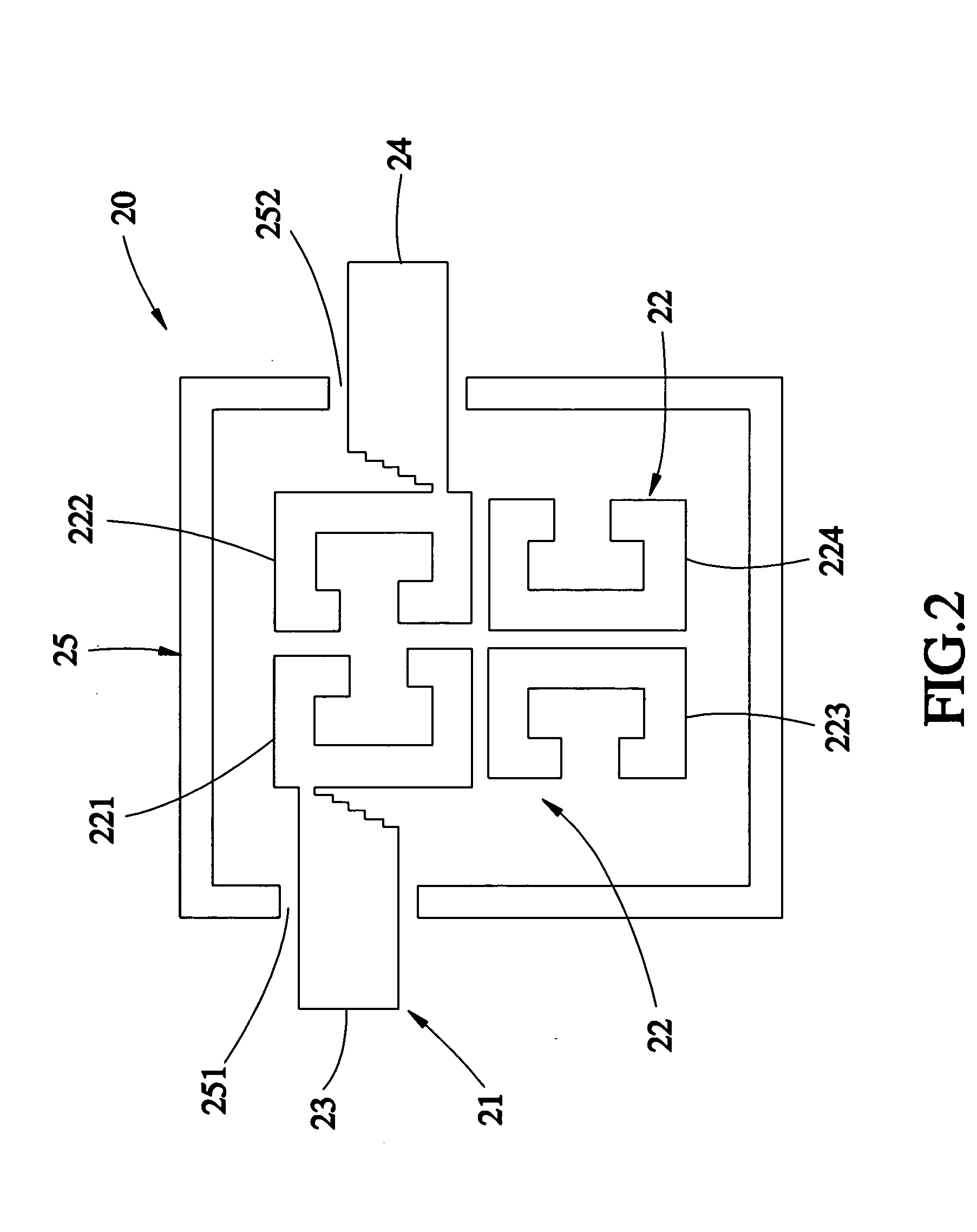
[0015]As shown in FIG. 2, the printed circuit 20 is a general type of the printed CQ (Cascade Quadruplet) filter, comprising a signal circuit 21 and a grounding circuit 25. The signal circuit 21 has four resonators 22, an input terminal 23, and an output terminal 24. The input terminal 23 and the output terminal 24 are for the input and output of RF (Radio Frequency) signal respectively. Each resonator 22 is a resonant cavity formed of a C-shaped half-wavelength transmission line. Further, the first resonator 221 and the second resonator 222 are magnetically coupled to each other and respectively connected to the input terminal 23 and the output...

second embodiment

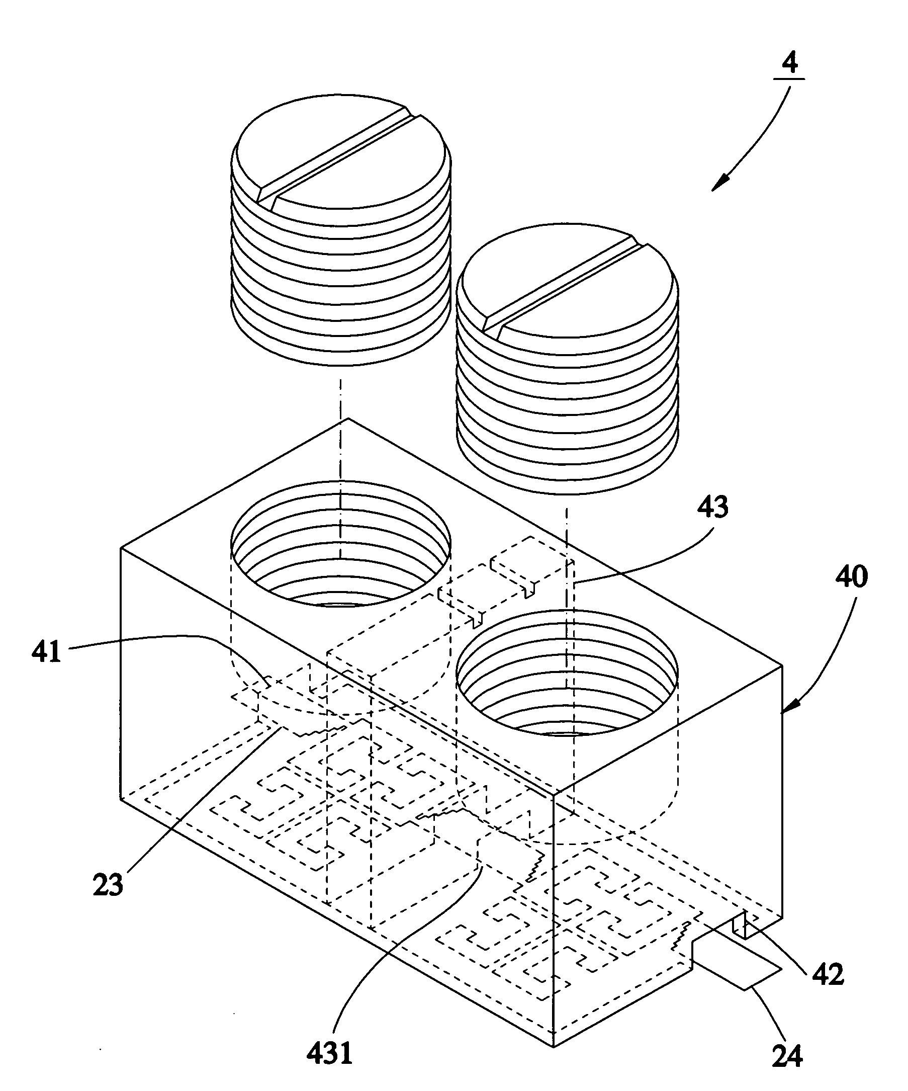
[0018]Further, since the present invention uses a simple structure to effectively adjust and improve the selectivity of the filter, a high-frequency filter of multi-order network can be achieved by simply cascading multiple high-frequency filters with same structure of the present invention. FIG. 2 shows a high-frequency filter 4 in accordance with the present invention, which cascades two filters with the same structure provided in the previous embodiment. According to this embodiment, the metal shielding 40 is the combination of the metal shells of two joined tuners, having two bottom through holes 41 and 42 for the passing of the input terminal 23 and the output terminal 24 respectively, and a partition wall 43, which is equivalent to the abutted sidewalls of the metal shells of the two joined tuners and consequently formed a bottom through hole 431 for allowing electric connection of the two CQ filters. FIG. 5 shows the frequency response characteristic of the high-frequency fil...


PUM


Abstract

A high-frequency filter for providing an analog signal with a predetermined bandwidth includes a printed circuit on which a tuner is covered. The printed circuit includes a signal circuit having a plurality of resonators magnetically or electrically coupled with each other, and a grounding circuit electrically connected to ground and arranged around the resonators. The tuner includes a shell made of a conductive metal, electrically connected to the grounding circuit and covered over the resonators such that an isolation chamber is defined between the shell and the resonators, and an adjustment member movably mounted in the shell and moveable relative to the resonators to adjust the dimension of the isolation chamber so as to further adjust a range of the bandwidth of the analog signal.

Description

BACKGROUND OF THE INVENTION[0001]1. Field of the Invention[0002]The present invention relates to a radio frequency circuit for wireless communication and more particularly, to a filter utilizing a printed circuit technology.[0003]2. Description of the Related Art[0004]Following fast development of wireless communication market, system demand for wide band communication keeps increasing. A bandpass filter with wide bandwidth is required for channel selection in transmitter and receiver of communication system. A high performance bandpass filter is the key point that determines system communication quality. A high performance bandpass filter has the characteristics of high selectivity and low insertion loss. The so-called selectivity here is the ability of discriminating between signals at different frequencies. A high selectivity filter effectively attenuates side band signals, shortens the guard band width between desired bands, and allows efficient use of the radio frequency. This ...

Claims


Application Information

Patent Timeline
Patent Type & Authority Applications(United States)
IPC IPC(8): H01P1/203
CPCH01P1/20381
Inventor JUANG, YU-RUKE, CHING-LAI
Owner PRIME ELECTRONICS & STATELLITCS
Why Eureka
Try Eureka