Nuclear fuel assemblies with structural support replacement rods

a technology of structural support and fuel assemblies, which is applied in the direction of nuclear elements, nuclear engineering problems, greenhouse gas reduction, etc., can solve the problems of inadequate geometric and dimensional stability of standard vver fuel assemblies, insufficient support of current fuel management schemes, and insufficient support of standard vver fuel assembly designs. achieve high burn-up fuel management, enhance structural stability, and reduce the effect of neutron capture cross-section

Inactive Publication Date: 2007-07-19
WESTINGHOUSE ELECTRIC CORP
View PDF10 Cites 21 Cited by
  • Summary
  • Abstract
  • Description
  • Claims
  • Application Information

AI Technical Summary

Benefits of technology

[0008] The present invention provides novel fuel assemblies for use with PWR nuclear reactors and power plants, and in particular, VVER nuclear reactors. The fuel assemblies offer enhanced structural stability, skeletal rigidity, and distortion resistance to support high burn-up fuel management. Each fuel assembly may include a plurality of fuel rods, a plurality of control rods and guide thimbles, at least one instrumentation tube, and a plurality of grids. At least one fuel rod is replaced with a structural support replacement rod made from zirconium

Problems solved by technology

Unfortunately, standard VVER fuel assemblies may not provide adequate geometric and dimensional stability during irradiation, or sufficient resistance to fuel assembly distortion.
Fuel assembly bow and twist measurements, handling incidents, and incomplete rod insertion (IRI) events indicate that standard VVER fuel assembly designs may not adequately support current fuel management schemes with four annual cycles (i.e., four year long fuel cycles, during which time a region of fuel assemblies may remain within the reactor core).
Moreover,

Method used


Image

  • Nuclear fuel assemblies with structural support replacement rods
  • Nuclear fuel assemblies with structural support replacement rods
  • Nuclear fuel assemblies with structural support replacement rods

Examples


example

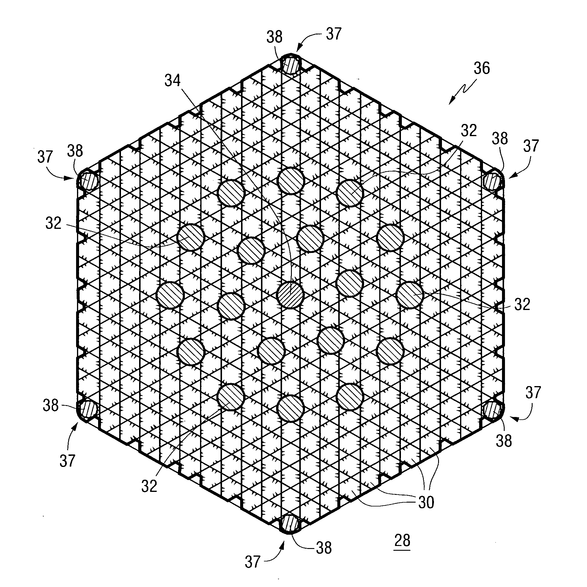
[0043]FIG. 8 presents four different structural support replacement rod configurations or patterns in accordance with the invention. The patterns are denoted in the legend of FIG. 8 as Pattern A, Pattern B, Pattern C, and Pattern D. For each pattern, six structural support replacement rods made from zirconium were positioned in the fuel assembly 36 having hexagonal geometric array 36. For Pattern A, it was assumed that the structural support replacement rods were positioned adjacent to the corners 37 of the hexagonal array 36. For Pattern B, it was assumed that the structural support replacement rods were positioned one fuel rod 30 away from the corners 37 of the hexagonal array 36. For Pattern C, it was assumed that the structural support replacement rods were positioned two fuel rods 30 away from the corners 37 of the hexagonal array 36. For Pattern D, it was assumed that the structural support replacement rods were positioned approximately halfway in between the corners 37 of the...


PUM


Abstract

The present invention provides novel fuel assemblies for use with PWR nuclear reactors and power plants, and in particular, VVER nuclear reactors. The fuel assemblies offer enhanced structural stability, skeletal rigidity, and distortion (bow and twist) resistance to support high burn-up fuel management. Each fuel assembly may include a plurality of fuel rods, a plurality of control rods and guide thimbles, at least one instrumentation tube, and a plurality of grids. At least one fuel rod is replaced with a structural support replacement rod made from zirconium (Zr) alloy, stainless steel, or any other suitable material. The structural support replacement rod may be hollow or solid. The structural support replacement rods are preferably disposed at or about the periphery, and in some cases, the corners of the geometric array, which is preferably a hexagon or square.

Description

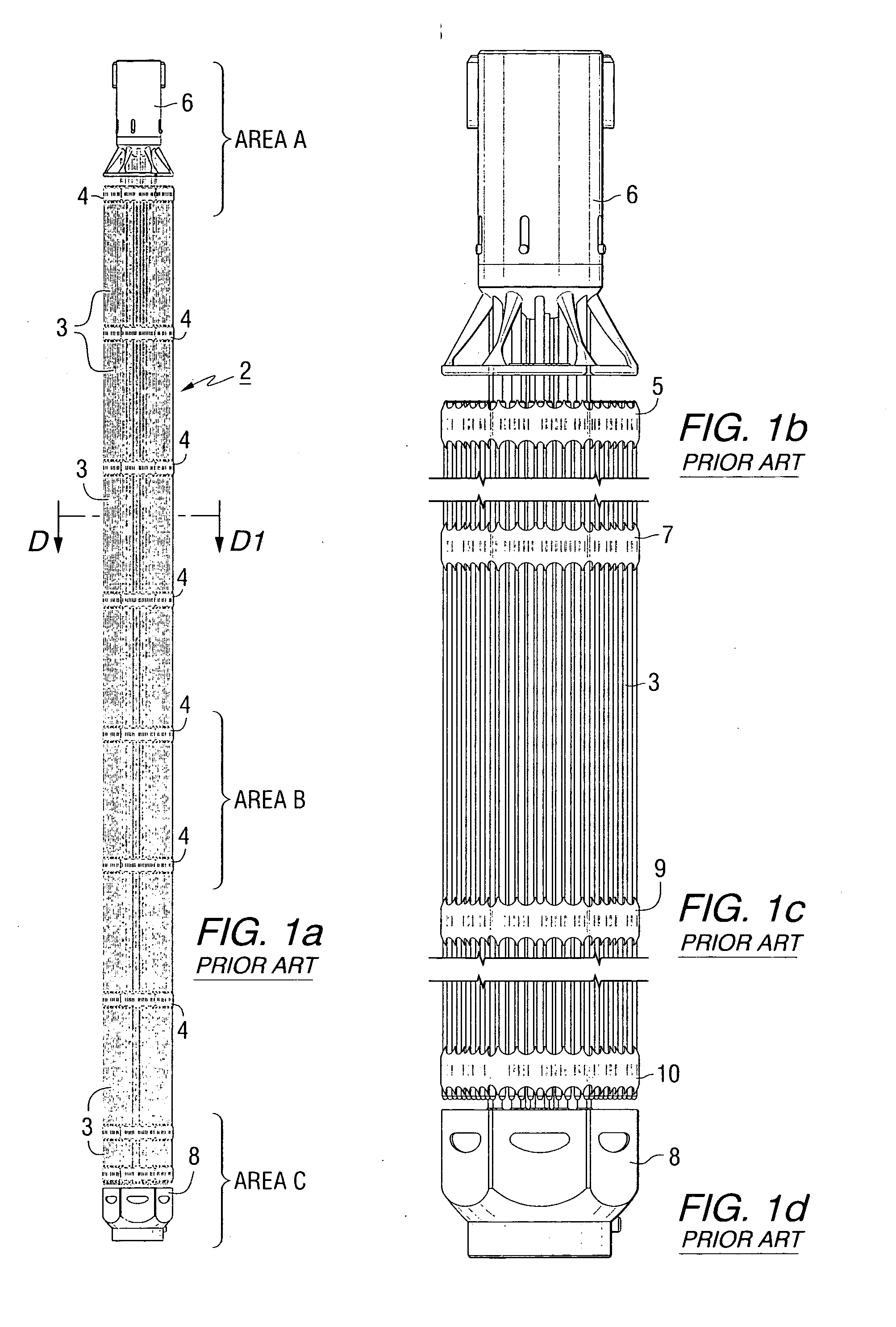
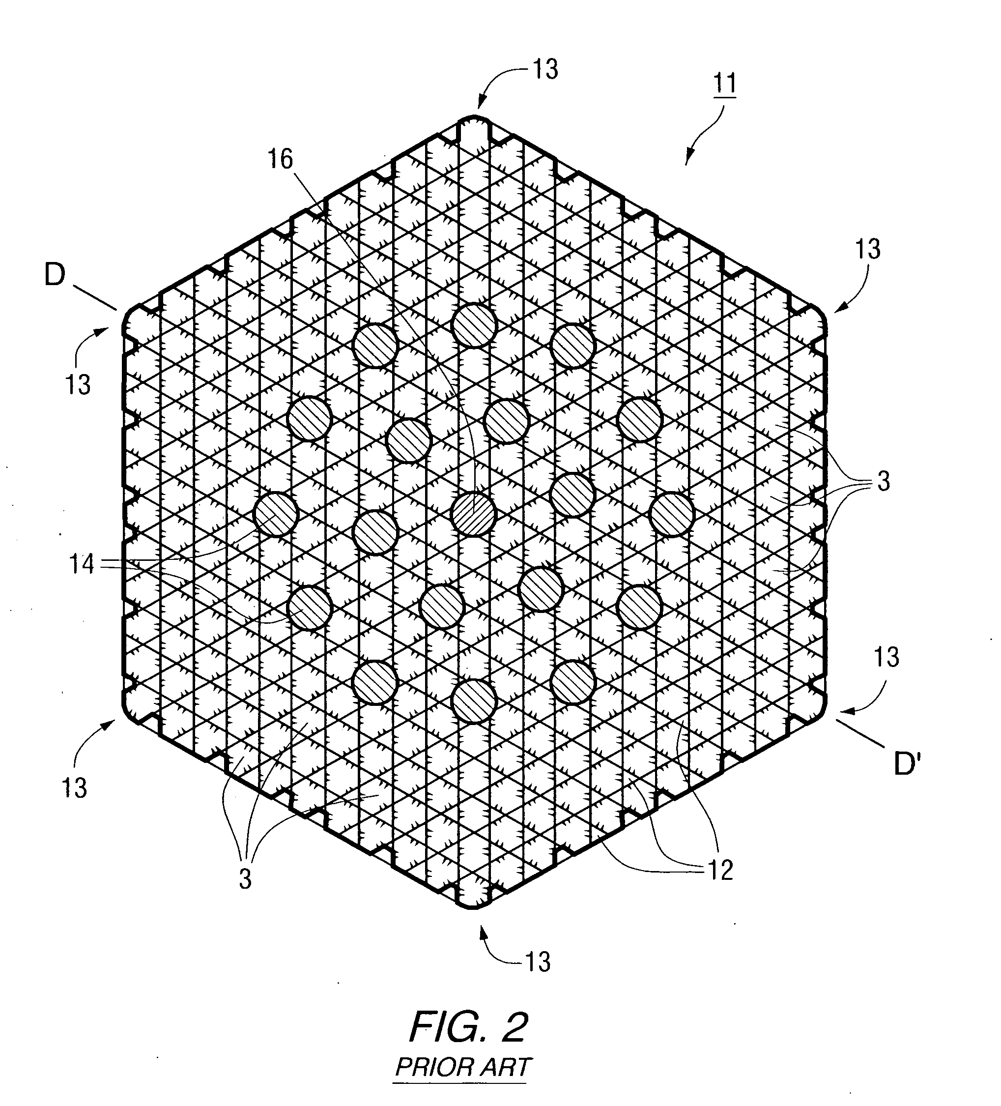
FIELD OF THE INVENTION [0001] The present invention relates to fuel assemblies for nuclear reactors and power plants and, more particularly, to fuel assemblies in which at least one fuel rod has been replaced with a structural support replacement rod. BACKGROUND INFORMATION [0002] Nuclear power plants typically utilize water to remove the heat created by the fission of an element such as uranium within the nuclear reactor. In a pressurized water reactor (PWR), heat is removed from the reactor by water flowing in a closed pressurized loop. The heat is transferred to a second water loop through a heat exchanger. The second loop is kept at a lower pressure, allowing the water to boil and create steam. The steam is used to turn a turbine-generator and produce electricity. Afterward, the steam is condensed into water and returned to the heat exchanger. [0003] The Voda-Vodyanoi Energetichesky Reaktor (VVER) is the Russian version of a PWR. FIG. 1a presents an elevational view of a standar...

Claims


Application Information

Patent Timeline
IPC IPC(8): G21C3/34
CPCG21C3/32G21Y2002/104G21Y2002/206Y02E30/40G21Y2002/304G21Y2004/30G21Y2002/303Y02E30/30
Inventor ALESHIN, YURIYSPARROW, JAMES A.DRUDY, KEITH J.
Owner WESTINGHOUSE ELECTRIC CORP
Why Eureka
Try Eureka