Optical sensing in a directional MEMS microphone

a technology of optical sensing and directional mems, which is applied in the field of micromachined differential microphones and optical interferometry, can solve the problems of compromising the effectiveness of sound detection, affecting the speech intelligibility of the speaker, and the mechanical design of the diaphragm, so as to reduce external acoustic noise and improve speech intelligibility

Inactive Publication Date: 2007-07-19
THE RES FOUND OF STATE UNIV OF NEW YORK +1
View PDF11 Cites 84 Cited by
  • Summary
  • Abstract
  • Description
  • Claims
  • Application Information

AI Technical Summary

Benefits of technology

[0021] In accordance with the present invention, there is provided a microphone having optical means for converting the sound-induced motion of the microphone diaphragm into an electronic signal. A diffraction device (e.g., a diffraction grating or, in alternate embodiments, inter-digitated fingers) is integrated with the microphone diaphragm to implement an optical interferometer which has the sensitivity of a Michelson interferometer. Because of the unique construction, the bulky and heavy beam splitter normally required in a Michelson interferometer is eliminated allowing a miniature, lightweight microphone to be fabricated. The microphone has a polysilicon diaphragm formed as a silicon substrate...

Problems solved by technology

This voltage creates practical constraints on the mechanical design of the diaphragm that compromise its effectiveness in detecting sound.
Specifically, inherent in the capacitive sensing configuration are a few limitations.
First, viscous damping caused by air between the diaphragm and the back plate can have a significant negative effect on the response.
Moreover, due to the viscosity of air, a significant source of microphone self noise is introduced.
Third, while the electrical sensitivity is proportional to the bias voltage, when the voltage exceeds a critical value, the attractive force causes the diaphragm to collapse against the back plate.
Theoretically, this noise can be reduced by increasing the bias voltage, Vb, or by reducing the diaphragm stiffness, k. Unfortunately, these parameters cannot be adjusted independently because the forces that are created by the biasing electric field can caus...

Method used


Image

  • Optical sensing in a directional MEMS microphone
  • Optical sensing in a directional MEMS microphone
  • Optical sensing in a directional MEMS microphone

Examples


Embodiment Construction

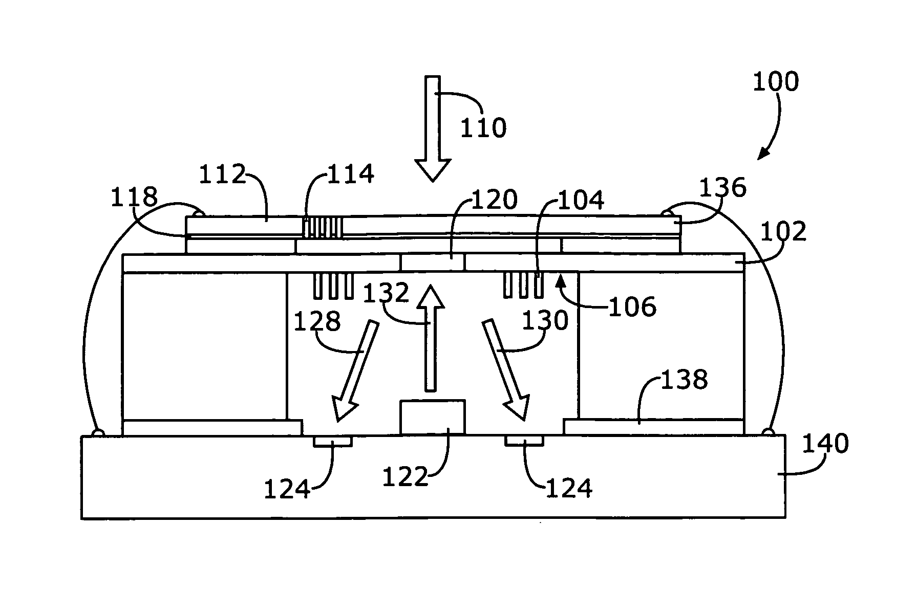
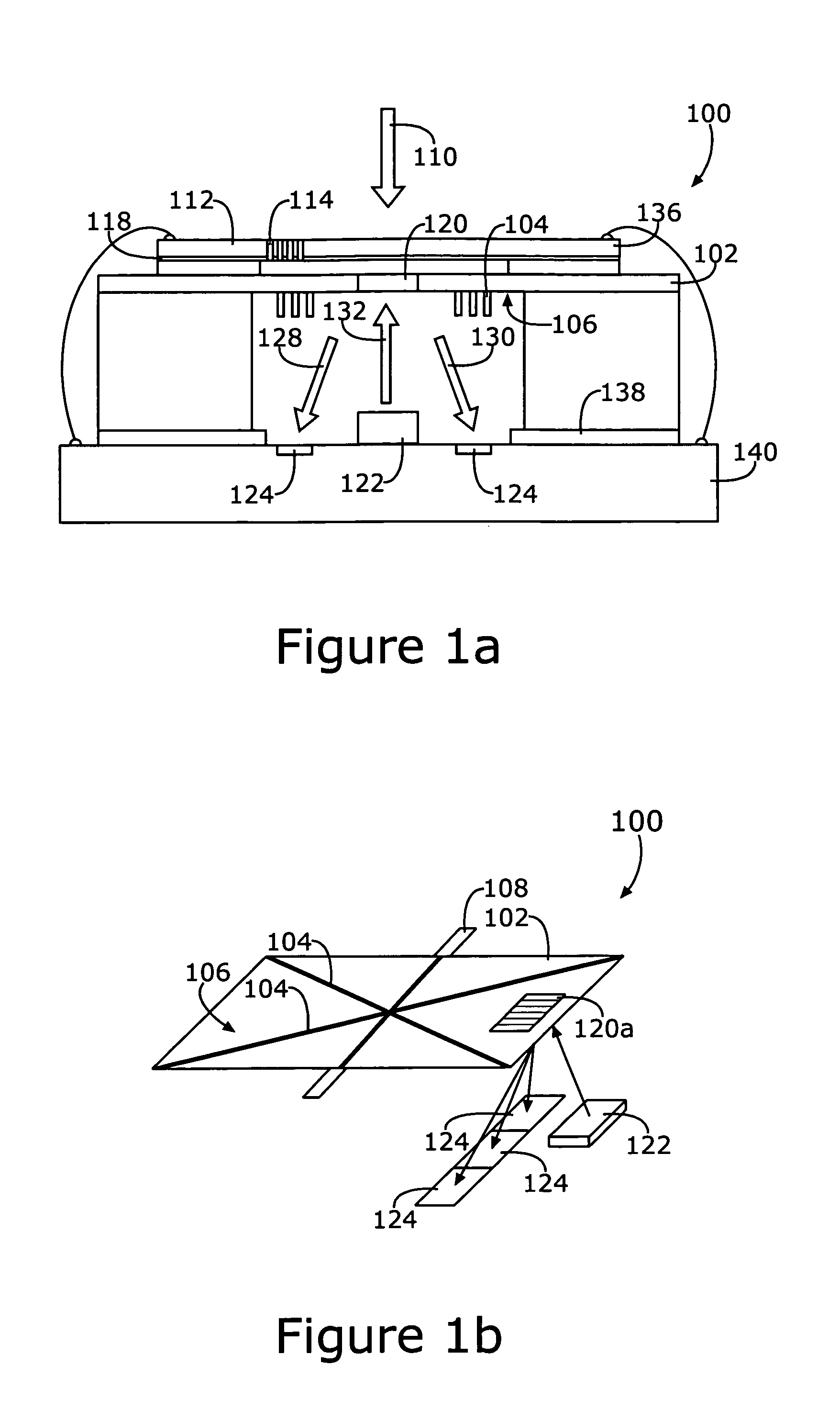
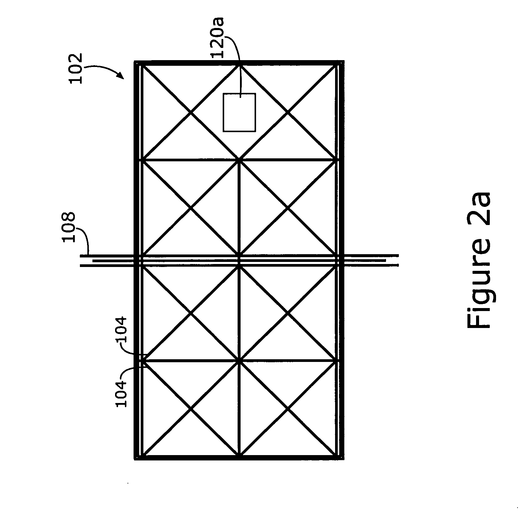
[0032] Generally speaking, the present invention is a directional microphone incorporating a diaphragm, movable in response to sound pressure and an optical sensing mechanism for detecting diaphragm displacement. The diaphragm of the microphone is designed to respond to pressure gradients, giving it a first order directional response to incident sound. This mechanical structure is integrated with a compact optical sensing mechanism that uses optical interferometry to generate an electrical output signal representative of the sound impinging upon the microphone's diaphragm. The novel structure overcomes adverse effects of capacitive sensing of microphones of the prior art.

[0033] One of the main objectives of the present invention is to provide a differential microphone suitable for use in a hearing aid and which uses optical sensing in cooperation with a micromachined diaphragm. Of course other applications for sensitive, miniature, directional microphones are within the scope of th...


PUM


Abstract

A microphone having an optical component for converting the sound-induced motion of the diaphragm into an electronic signal using a diffraction grating. The microphone with inter-digitated fingers is fabricated on a silicon substrate using a combination of surface and bulk micromachining techniques. A 1 mm×2 mm microphone diaphragm, made of polysilicon, has stiffeners and hinge supports to ensure that it responds like a rigid body on flexible hinges. The diaphragm is designed to respond to pressure gradients, giving it a first order directional response to incident sound. This mechanical structure is integrated with a compact optoelectronic readout system that displays results based on optical interferometry.

Description

RELATED APPLICATIONS [0001] The present application is related to U.S. Pat. No. 6,788,796 for DIFFERENTIAL MICROPHONE, issued Sep. 7, 2004; and copending U.S. patent applications, Ser. No. 10 / 689,189 for ROBUST DIAPHRAGM FOR AN ACOUSTIC DEVICE, filed Oct. 20, 2003, and Ser. No. 11 / 198,370 for COMB SENSE MICROPHONE, filed Aug. 5, 2005, all of which are incorporated herein by reference. FIELD OF THE INVENTION [0002] The present invention pertains to microphones and, more particularly, to micromachined differential microphones and optical interferometry to produce an electrical output signal. BACKGROUND OF THE INVENTION [0003] Low noise and low power are essential characteristics for hearing aid microphones. Most high performance microphones, and particularly miniature microphones, consist of a thin diaphragm along with a spaced apart, parallel back plate electrode; they use capacitive sensing to detect diaphragm motion. This permits detecting the change in capacitance between the pres...

Claims


Application Information

Patent Timeline
IPC IPC(8): H04R9/08
CPCH04R23/008H04R23/006
Inventor MILES, RONALD N.DEGERTEKIN, F. LEVENT
Owner THE RES FOUND OF STATE UNIV OF NEW YORK
Why Eureka
Try Eureka