Supercharge Your Innovation With Domain-Expert AI Agents!

Automatic power output control circuit

a power output control and circuit technology, applied in gain control, digital transmission, baseband system details, etc., to achieve the effect of suppressing the variation in the power output level of a signal output, low loop gain for power output control, and high loop gain

Inactive Publication Date: 2007-07-26
RICOH ELECTRONIC DEVICES CO LTD
View PDF4 Cites 12 Cited by
  • Summary
  • Abstract
  • Description
  • Claims
  • Application Information

AI Technical Summary

Benefits of technology

[0007]The present invention has been made to solve the above-described problems, and has as its object to keep the control characteristic for APC good, regardless of whether a selected power output level is low or high and prevent variation in the power output level of and occurrence of ringing in a signal output from a power amplifier.
[0009]According to the present invention with this structure, if the power output level set in the power amplifier is low, the loop gain for power output control is made high. This suppresses variation in the power output level of a signal output from the power amplifier. On the other hand, if the power output level set in the power amplifier is high, the loop gain for power output control is made low. This suppresses occurrence of ringing in a signal output from the power amplifier. As described above, according to the present invention, it is possible to keep the control characteristic for power output good regardless of whether the selected power output level is low or high and suppress variation in power output level and ringing.

Problems solved by technology

However, if an APC loop gain is kept constant in a system capable of selecting one of a plurality of power output levels, the following problems occur.

Method used


Image

  • Automatic power output control circuit
  • Automatic power output control circuit
  • Automatic power output control circuit

Examples


Embodiment Construction

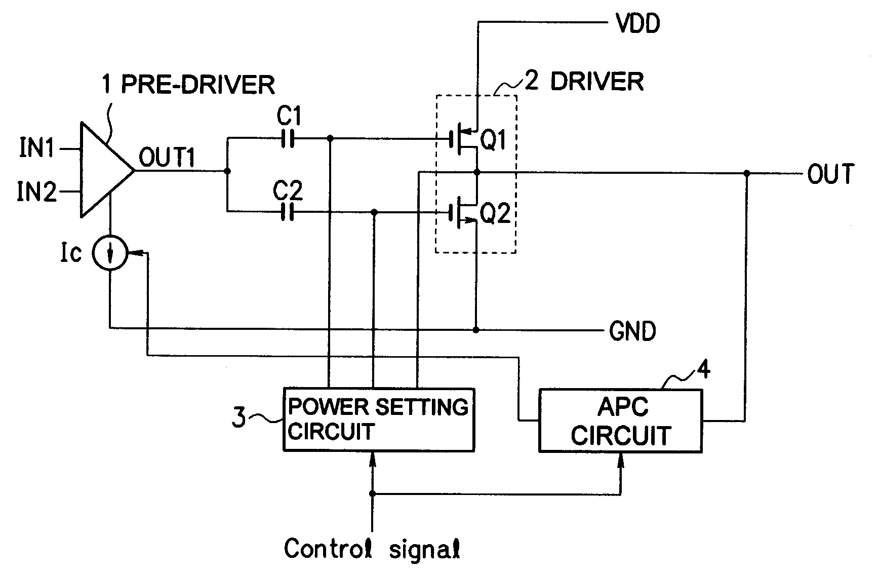
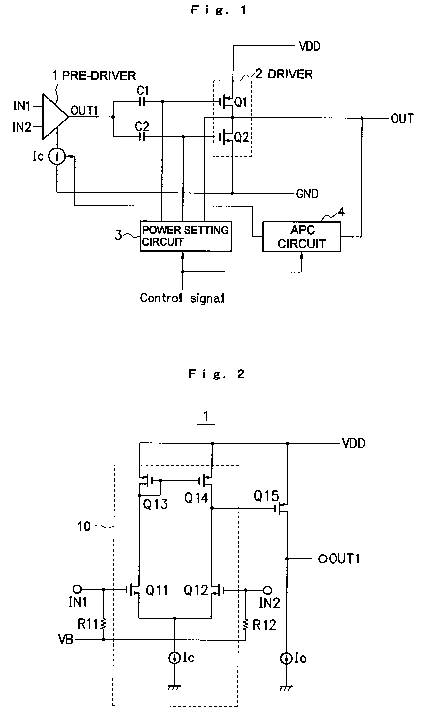
[0019]An embodiment of the present invention will be explained below with reference to the drawings. FIG. 1 is a diagram showing an example of the configuration of a power amplifier according to this embodiment. As shown in FIG. 1, the power amplifier of this embodiment comprises a pre-driver 1 which amplifies the voltage of an input signal to a desired level, a driver 2 which amplifies the power of a signal output from the pre-driver 1 to a desired level, a power setting circuit 3 which sets the power output level (output voltage) of the power amplifier, and an APC circuit 4 which controls the power output level of the power amplifier to be constant at a set level.

[0020]FIG. 2 is a diagram showing an example of the configuration of the pre-driver 1. In FIG. 2, reference numeral 10 denotes a differential amplifier circuit which comprises a differential pair composed of two transistors Q11 and Q12, transistors Q13 and Q14 constituting a current mirror circuit for taking out, as a sin...


PUM


Abstract

This invention includes a gain control section 13 capable of changing an APC loop gain according to a power output level set in a power amplifier to allow suppression of variation in power output level when the power output level is low and suppression of occurrence of ringing when the power output level is high by making the loop gain high when the power output level is low and making the loop gain low when the power output level is high.

Description

BACKGROUND OF THE INVENTION[0001]1. Field of the Invention[0002]The present invention relates to an automatic power control circuit and, more particularly, to one preferably used as an automatic power output control circuit applied to a power amplifier configured to be capable of selecting a desired one of a plurality of power output levels.[0003]2. Description of the Related Art[0004]A conventional radio transceiver uses an automatic power output control circuit (APC (Automatic Power Control) circuit) to keep power radiated from an antenna at the time of transmission constant. The APC circuit controls the intensity of radio waves radiated from the antenna by finely adjusting the gain of a high-frequency power amplifier in an RF (Radio Frequency) circuit section of the radio transceiver (see, e.g., Japanese Patent Laid-Open No. 2002-94392 and Japanese Patent Laid-Open No. 2002-280853).[0005]Some of recent radio transceivers such as a transmitter system are capable of selecting a des...

Claims


Application Information

Patent Timeline
Patent Type & Authority Applications(United States)
IPC IPC(8): H03F3/45
CPCH03F1/02H03F3/3022H03F3/45183H03G3/3042H03F2203/30015H03F2203/45594H03F2203/45726H03F3/45192
Inventor ISHIGURO, KAZUHISA
Owner RICOH ELECTRONIC DEVICES CO LTD
Features
  • R&D
  • Intellectual Property
  • Life Sciences
  • Materials
  • Tech Scout
  • Unparalleled Data Quality
  • Higher Quality Content
  • 60% Fewer Hallucinations
Learn More