
Post (power on self test) debug system and method

a debugging system and self-testing technology, applied in error detection/correction, instruments, digital computers, etc., can solve problems such as hardware errors or bios routine errors, failure of server system operation, and inability to use large-scale debugging software for debugging, etc., to achieve fast and efficient fine-grained reason for errors, simple and easy operation, and low debug cost

Inactive Publication Date: 2007-07-26
INVENTEC CORP
View PDF15 Cites 29 Cited by
  • Summary
  • Abstract
  • Description
  • Claims
  • Application Information

AI Technical Summary

Benefits of technology

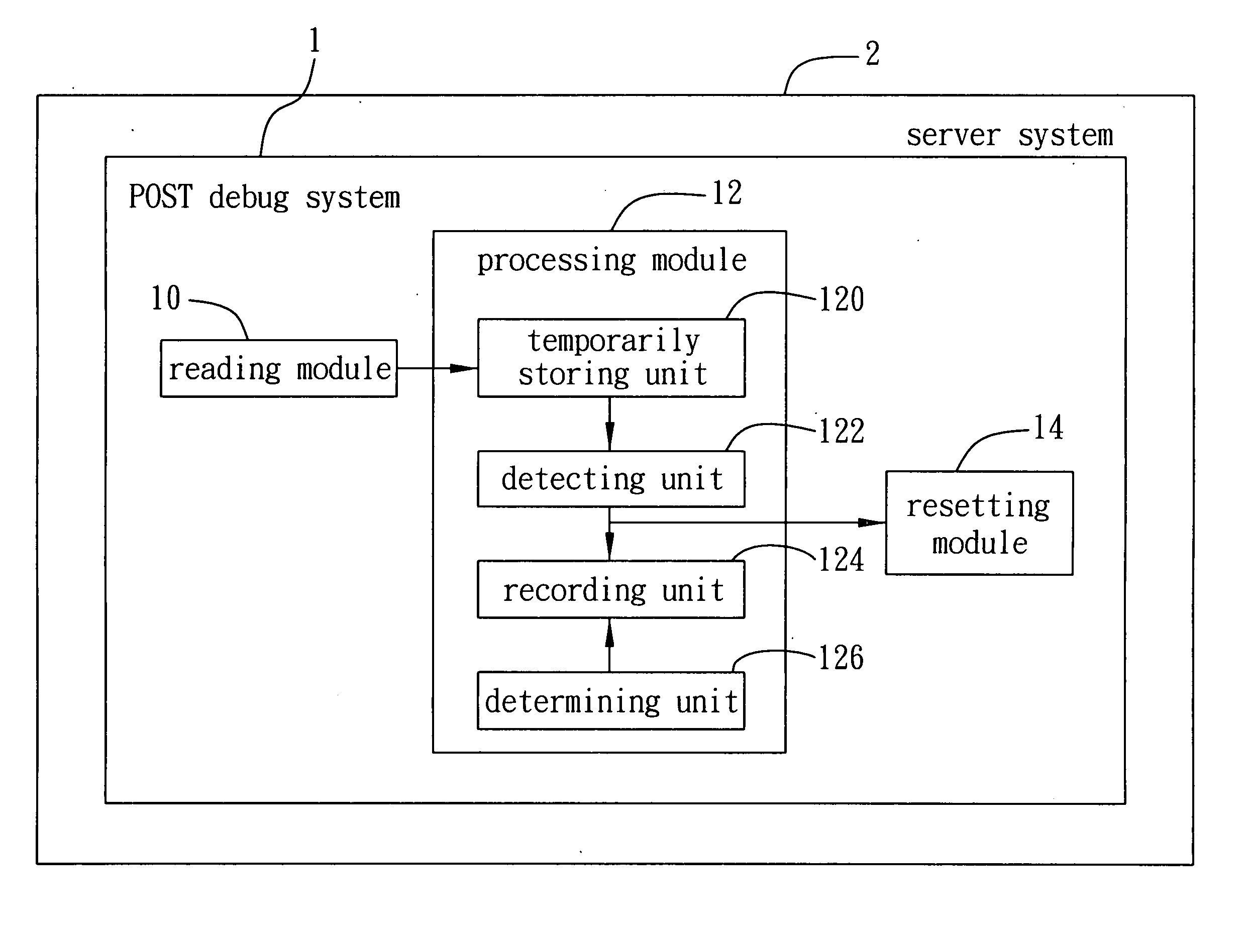
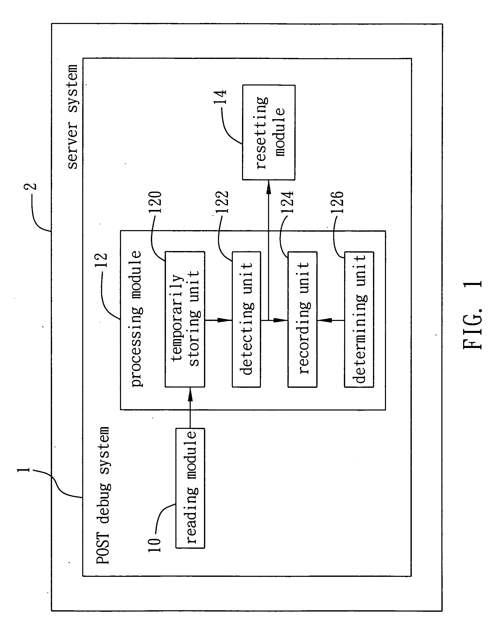
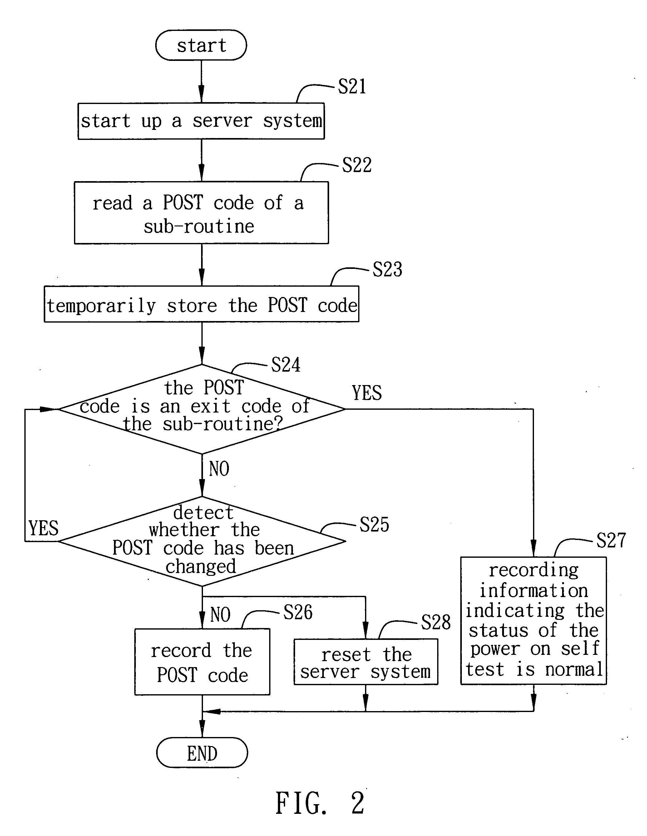
The present invention provides a simple and easy to operate POST debug system and method for electronic devices. The system includes a reading module for reading a POST code of a sub-routine and outputting it, and a processing module for temporarily storing the POST code and detecting if it has been changed. The recorded POST code can be used for debugging the system. The processing module also determines if the POST code is an exit code of the sub-routine and sends information indicating the power on self test is normal. The system does not require a peripheral debug device like a POST card, reducing the cost. The present invention provides greater flexibility for the motherboard layout of the server system and saves time and labor in repairing errors.

Problems solved by technology

However, some errors such as hardware errors or BIOS routine errors may occur during the initializing process.
Such errors can lead to fail operation of the server system.
Since the BIOS routine code is small in size and the operation system (OS) has not been loaded to the server system during the initializing process, it is impossible to use large size debug software for debugging.
Instead, a user only can search errors from original codes or use some specific devices for debugging hardware at a rather low speed.
However, the above debug system needs a POST card having a decode circuit for decoding the POST code and a display means such as a LED for displaying the debug status, thereby increasing the debug cost.
Further, both a PCI slot for receiving the POST card and the LED need to be disposed on the motherboard, which thus limit the motherboard layout flexibility.
Furthermore, when the server system begins to reset because of some errors of the routines, the POST code value is easy to lose, which accordingly increases the debug difficulty for developers.
Although combining an ISA bus or a LPT bus with a POST card is also possible for system debugging, such a method is rather complex and difficult to implement.

Method used


Image

  • Post (power on self test) debug system and method
  • Post (power on self test) debug system and method
  • Post (power on self test) debug system and method

Examples


Embodiment Construction

[0025] Hereunder, embodiments of the present invention will be described in full detail with reference to the accompanying drawings.

[0026]FIG. 1 is a block diagram of a POST (power on self test) debug system 1 of the present invention. The POST debug system 1 can be applied to an electronic device such as a server system 2, although it is not limited thereto. As shown in FIG. 1, the POST debug system 1 comprises a reading module 10 and a processing module 12.

[0027] The reading module 10 is used to read a POST code of a sub-routine to be executed when the server system 2 is started up to execute a power on self test. The reading module 10 then outputs the POST code to the processing module 12 for further processing. In the present invention, the reading module 10 is a basic input / output system (BIOS) of the server system 2, which comprises a plurality of sub-routines for executing the power on self test. Therein, each of the sub-routines has one and only POST code for testing a dif...


PUM


Abstract

A POST (power on self test) debug system and method applicable to an electronic device is proposed. First, a reading module reads a POST code of a sub-routine to be executed when the electronic device is started up to execute a power on self test, and sends the POST code to a processing module. When the processing module receives the POST code, the processing module temporarily stores the POST code and detects whether the temporarily stored POST code has been changed at a predefined time interval. If no, the processing module records the temporarily stored POST code such that a user can fine reason for error according to the recorded POST code and repair the system timely. Such a debug system is simple and easy to implement.

Description

BACKGROUND OF THE INVENTION [0001] 1. Field of the Invention [0002] The present invention relates to a debug system and method, and more particularly to a POST (power on self test) debug system and method which can be applied to electronic devices such as server systems. [0003] 2. Description of Related Art [0004] On startup of a server system, a central processing unit (CPU) reads routines stored on a BIOS (basic input output system) chip of the motherboard for initializing hardwares within the server system. Through the routines, registers of the CPU are tested first and then peripheral devices such as a dynamic random access memory (DRAM), a motherboard chipset, a display card and so on are initialized. The initialization of the hardwares includes adding values to registers or changing register values according to some specific technology files such that chipset memory, I / O functions and so on can operate normally. [0005] However, some errors such as hardware errors or BIOS routi...

Claims


Application Information

Patent Timeline
Patent Type & Authority Applications(United States)
IPC IPC(8): G06F11/00
CPCG06F11/2284
Inventor SHIH, WH
Owner INVENTEC CORP
Learn More