Unlock instant, AI-driven research and patent intelligence for your innovation.

Method of making a tool component

a tool and component technology, applied in the field of making tool components, can solve the problems of abrasive compact layer development, brittle abrasive compact layer, and problems in us

Inactive Publication Date: 2007-08-02
SIGALAS IAKOVOS +1
View PDF1 Cites 12 Cited by
  • Summary
  • Abstract
  • Description
  • Claims
  • Application Information

AI Technical Summary

Benefits of technology

[0007] In one form of the invention, the material of one source comprises a mass of discrete ultra-hard abrasive particles such as diamond or cubic boron nitride in a binder. The material of the other source comprises a mass of discrete abrasive particles different to those of the material of the first source, for example carbide particles, in a binder. By controlling the quantity of material from each source which is delivered to the mixing zone, different mixtures of the two abrasives can be created. In this way, layers, e.g. one on top of the other, can be produced which differ from their neighbours in abrasive particle composition. These layers, on sintering, form non-homogeneous regions in the working portion of a tool component.

Problems solved by technology

Abrasive compacts tend to be brittle and in use they are frequently supported by being bonded to a cemented carbide substrate or support.
Where the composite abrasive compact has a thick abrasive compact layer, particularly a thick diamond compact layer, residual tensile stresses in the abrasive compact layer develop giving rise to problems in use.
These stresses contribute to delamination and fracture of the compact layer in use.

Method used


Image

  • Method of making a tool component

Examples


example 1

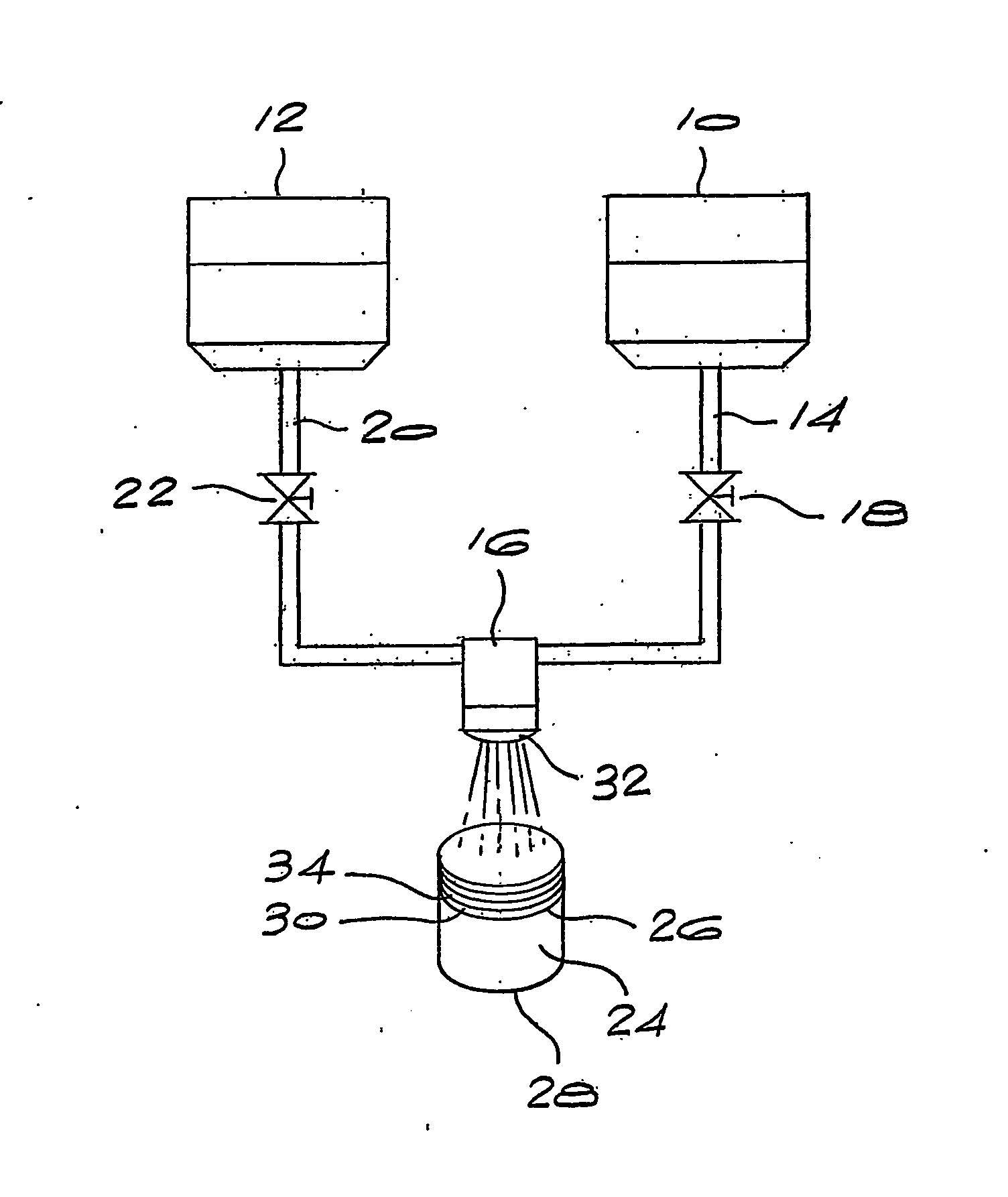
[0019] A cylindrical-shaped component was prepared with a WC / diamond gradient in the axial direction using the wet powder spraying (WPS) method of the invention. The starting layer of the cylinder was a 4 mm layer of WC / Co. This was not prepared using the wet powder spraying method, but was rather pressed from commercially available powder at 100 MPa to obtain a strong, porous support for the subsequent layer deposition. This base layer was then strengthened further by a pre-sintering treatment under hydrogen at 600° C. The porosity of this layer was chosen to achieve a similar shrinkage behaviour to the overlying layers. The WC / Co grain composition was the same as that used in the diamond graded layers.

[0020] 49 gradient layers, each of approximately 100 μm thickness, with WC / diamond ratios varying in a monotonic manner were then deposited onto the WC / Co base by the WPS method. The diamond and WC particles were provided from separate containers, each in a suspension which included...

example 2

[0023] A cylindrical-shaped component was prepared with a diamond grain size gradient in the axial direction using a wet powder spraying (WPS) method similar to that described in Example 1. The diamond layer immediately adjacent to the WC / Co base layer was chosen to have an average grain size of approximately 25 μm, whilst the diamond layer in the uppermost layer was chosen to have an average grain size of approximately 4 μm. 50 layers were deposited, each of approximately 100 μm in thickness. The ratio of the two diamond grain sizes was altered in monotonic manner in 2% compositional intervals, from 100% 25 μm diamond at the base surface to 100% 4 μm diamond at the uppermost surface.

[0024] The mass composition of the WPS suspension did not alter signficantly from the base to the top layers, as the matrix material was consistently diamond throughout. The final compact was de-binded in a similar fashion to the compact generated in Example 1, and was then treated under high pressure ...

example 3

[0025] A cylindrical-shaped component was prepared with a gradient in diamond grain size and chemical composition in the axial direction using a wet powder spraying (WPS) method similar to that described in Example 1.

[0026] The layer immediately adjacent to the WC / Co base layer contained diamond grains of 25 μm in size and WC / Co particles of 2.5 μm in size in a 75:25 (diamond:WC / Co) mass ratio. The uppermost layer contained 100% diamond material of an average of 4 μm in size. The ratio of these two source compositions was altered in monotonic manner in 2% compositional intervals, from 100% (25 μm diamond / (WC / Co) mix) at the base surface to 100% 4 μm diamond at the uppermost surface.

[0027] The final compact was then de-binded in a similar fashion to the compact generated in Example 1, and was then treated under high pressure and high temperature to achieve a fully sintered compact with diamond to diamond bonding. Residual tensile stresses were once again significantly reduced in th...


PUM

PropertyMeasurementUnit
Massaaaaaaaaaa
Sizeaaaaaaaaaa
Particle sizeaaaaaaaaaa

Abstract

A method of producing a tool component comprising a working portion of bonded abrasive particles including a non-homogeneous region. The method includes the step of providing at least two sources of a material comprising abrasive particles in a suitable binder, the materials of the sources differing from each other. The material of one source may comprise diamond or cubic boron nitride particles, whilst the material of the other source may comprise carbide particles. Alternatively, the materials of the two sources may contain the same abrasive particle, such as diamond or cubic boron nitride particles, but in different particle sizes. The materials are delivered to a zone where mixing occurs, and the mixture is applied to a surface to produce a layer of the mixed materials on the surface, typically by spraying. By controlling the quantity of material from each source which is delivered to the mixing zone, different mixtures of the two abrasives can be created. In this way, layers, e.g. one on top of the other, can be produced which differ from their neighbours in abrasive particle composition. These layers, on sintering, form non-homogeneous regions in the working portion of a tool component.

Description

BACKGROUND OF THE INVENTION [0001] This invention relates to a method of making a tool component. [0002] Abrasive compacts are used extensively in cutting, milling, grinding, drilling, boring and other abrasive operations. Abrasive compacts consist of a mass of diamond or cubic boron nitride particles bonded into a coherent, polycrystalline conglomerate. The abrasive particle content of abrasive compacts is high and there is generally an extensive amount of direct particle-to-particle bonding. Abrasive compacts are made under elevated temperature and pressure conditions at which the abrasive particle, be it diamond or cubic boron nitride, is crystallographically stable. [0003] Diamond abrasive compacts are also known as polycrystalline diamond or PCD and cubic boron nitride abrasive compacts are also known as polycrystalline CBN or PCBN. [0004] Abrasive compacts tend to be brittle and in use they are frequently supported by being bonded to a cemented carbide substrate or support. Su...

Claims


Application Information

Patent Timeline
IPC IPC(8): B24D3/02B22F7/02B24D3/10B24D18/00C23C4/12C23C4/18C23C24/00C23C24/08C23C30/00
CPCB22F7/02C23C30/005B24D18/00C04B35/52C04B35/5626C04B2235/3847C04B2235/405C04B2235/427C04B2235/5436C04B2235/6582C04B2235/75C23C4/185C23C24/00C23C24/08B24D3/10
Inventor SIGALAS, IAKOVOSFRIES, ROBERT
Owner SIGALAS IAKOVOS