
Method of manufacturing plugged honeycomb structure and manufacturing apparatus of plugged honeycomb structure

Inactive Publication Date: 2007-08-09
NGK INSULATORS LTD
View PDF0 Cites 24 Cited by
  • Summary
  • Abstract
  • Description
  • Claims
  • Application Information

AI Technical Summary

Benefits of technology

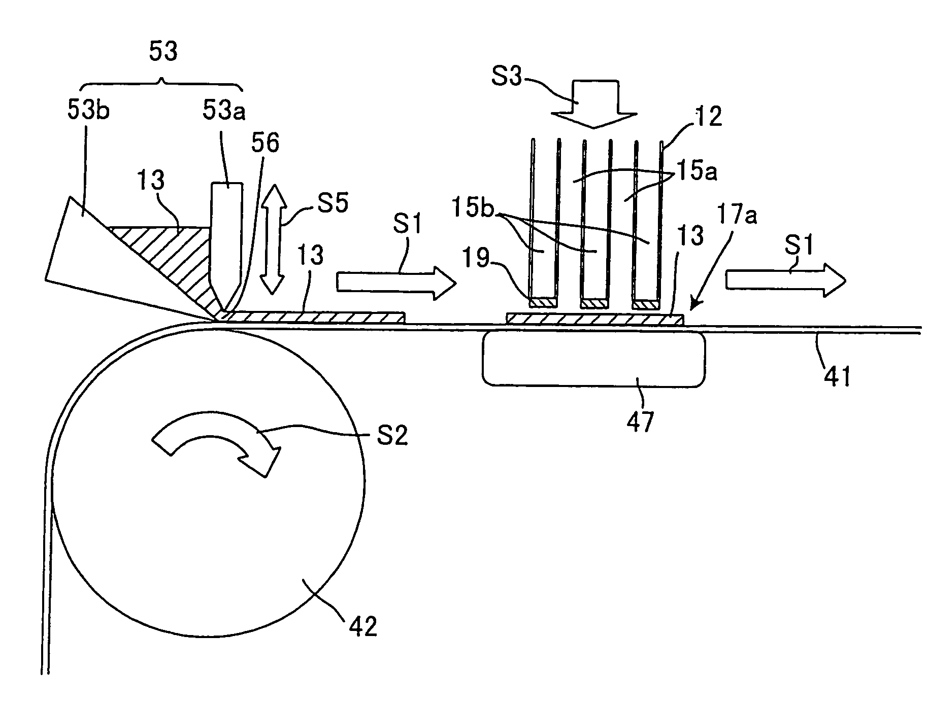
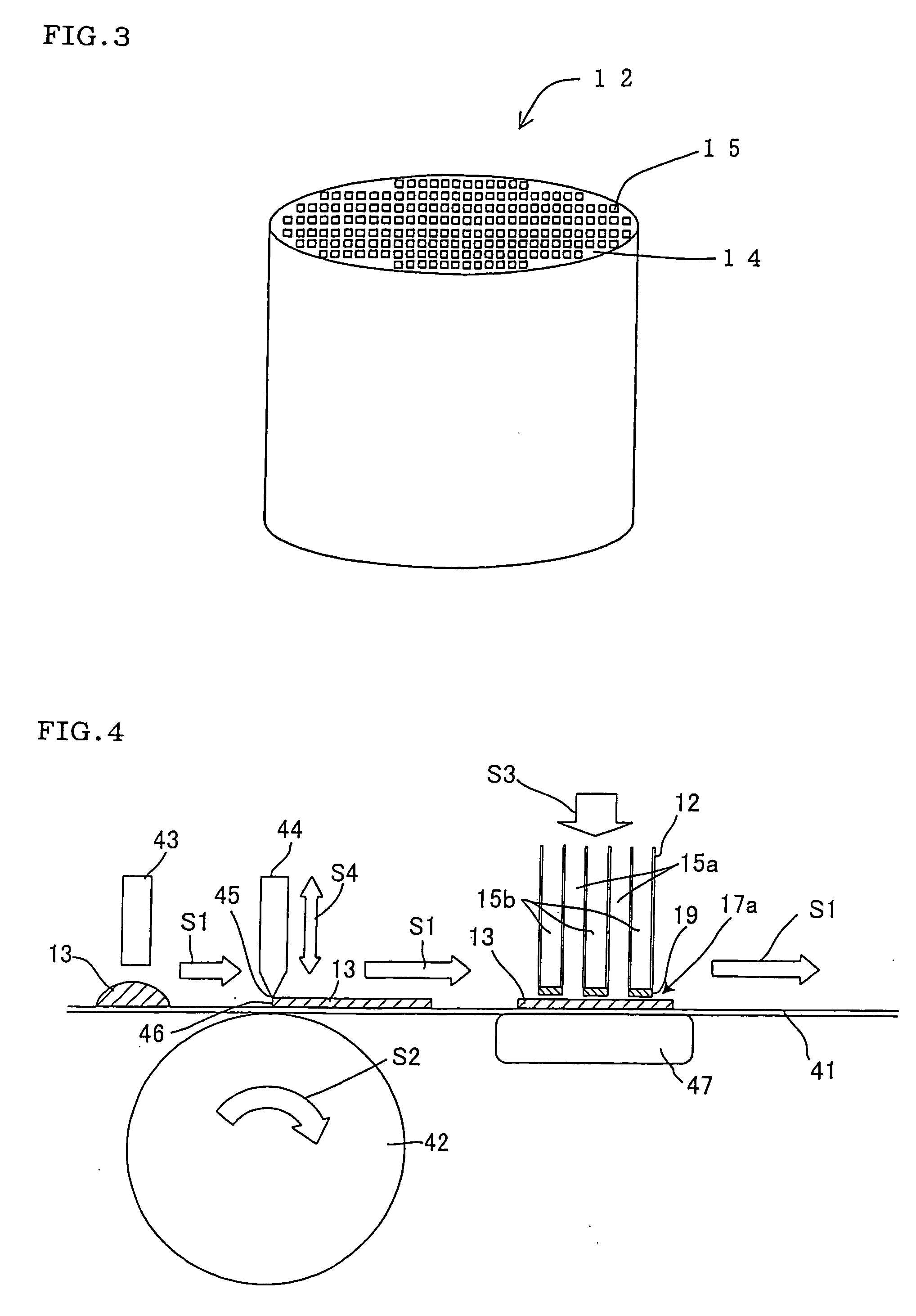
[0030] In the first manufacturing method of the present invention, since a plugging material is supplied on a plane and the plugging material on the plane is leveled by moving the leveling member having a straight-line side or by moving the plane to allow the leveling member to pass in such a manner that a side of the leveling member is in parallel with the plane, it is not necessary to level the plugging material in a container, and thickness of the plugging material on the plane can be made uniform. In addition, by positioning the leveled member on a plane and adjusting a gap between the leveled plugging member and the plane, thickness of the plugging material on the plane can easily be adjusted, and depth of the plugging member can simply be adjusted.
[0031] In the second method of the present invention, since a plugging material supplier having a slit aperture is disposed on a plane in parallel with the plane and supplying a plugging material on the plane with moving the plugging material supplier or with moving the plane to supply the plugging member on the plane from the slit aperture of the plugging material supplier to level the plugging material on the plane, it is not necessary to level the plugging material in a container, and thickness of the plugging material on the plane can be made uniform. In addition, by adjusting width of the slit aperture of the plugging material supplier, thickness of the plugging material on the plane can easily be adjusted, and depth of the plugging member can simply be adjusted.
[0032] Since, in a conventional manufacturing method (plugging process), a plugging material (ceramic slurry) was stored in a container to fill the plugging material into the cells, the plugging material remains in the container after the filling, and time and effort were spent on washing of the container. However, since it is not necessary to level the plugging material in a container in the method for manufacturing a plugged honeycomb structure of the present invention (the first manufacturing method and the second manufacturing method), time and effort spent on washing of the container can be saved. In addition, by constituting a plane where the plugging material is supplied by the belt of the belt conveyer, recycling of the plugging material becomes easy, and it is possible to attempt to reduce an amount of the plugging material practically used and consumed.
[0033] Since the plugging material is of ceramic slurry containing a pore former in a preferable mode in a method for manufacturing a plugged honeycomb structure of the present invention, a shrunk dent (a defect of forming a depression on an end face of a plugging member) is inhibited from being caused, and the plugging member can easily be leveled. This is because, when a pore former is added to ceramic slurry, water contained in the ceramic slurry is inhibited from moving freely by the pore former and hardly absorbed by the honeycomb structure, and this suppresses a phenomenon of decreasing volume of the ceramic slurry to be the plugging members because water contained in the slurry is abruptly absorbed by the honeycomb structure. This effect can be obtained in good conditions in the case that the pore former is a foaming resin. In addition, since the plugging member becomes porous, a pressure loss of the plugged honeycomb structure is further reduced.
[0036] In a preferable mode of a method for manufacturing a plugged honeycomb structure of the present invention, a plane upon leveling the plugging material is horizontal, and a plane when an end face of the unplugged honeycomb structure is pressed against the leveled plugging material or when the leveled plugging material is pressed against an end face of the unplugged honeycomb structure is vertical. In such a mode, by keeping the end faces of the unplugged cylindrical honeycomb structure to face the horizontal directions, the leveled plugging material can easily be pressed against both the end faces of the honeycomb structure at the same time. That is, the honeycomb structure is transported in the state that it is laid (state that the end faces of the honeycomb structure face horizontal directions), and it is possible to fill the plugging material into the cells under pressure in both the end faces at the same time. In addition, it can be treated with only one time of drying. Therefore, one step is sufficient instead of conventional two steps, which is efficient. In addition, since only one drying step is required, energy can be saved. Further, equipment for realizing such a successive production method (a device for manufacturing a plugged honeycomb structure of the present invention) is simple. In a conventional method where a plugging material is filled into the cells under pressure in a state that the honeycomb structure is stood (state that the end faces of the honeycomb structure faces vertical directions), two filling steps are required because filling of the plugging material in cells of each end face of the honeycomb structure is conducted independently, and moreover each time of filling requires drying. Therefore, it needs a long production process, and more energy is spent on drying. According to a method for manufacturing a plugged honeycomb structure of the present invention, such problems can be solved.
[0037] A device for manufacturing a plugged honeycomb structure of the present invention is a device suitable for carrying out a method for manufacturing a plugged honeycomb structure of the present invention, and the aforementioned effect can be obtained by carrying out a method for manufacturing a plugged honeycomb structure of the present invention with using a device for manufacturing a plugged honeycomb structure of the present invention.

Problems solved by technology

However, in the case of manufacturing such a plugged honeycomb structure though the above plugging process, there arises a problem of easily having uneven depth of the plugging members.
It is noted, as one of the reasons why such a problem is caused, that it is difficult to level ceramic slurry as a plugging material in a container.
), and this tends to make the depth of the plugging members on the outer periphery side of the honeycomb structure shallow.

Method used


Image

  • Method of manufacturing plugged honeycomb structure and manufacturing apparatus of plugged honeycomb structure
  • Method of manufacturing plugged honeycomb structure and manufacturing apparatus of plugged honeycomb structure
  • Method of manufacturing plugged honeycomb structure and manufacturing apparatus of plugged honeycomb structure

Examples


example 1

[0093] A forming raw material prepared by adding water and a binder to a cordierite-forming raw material containing talc, kaolin, and alumina as main raw materials, and subjected to dispersion mixing and kneading was extruded into a cylindrical shape by a kneader and then subjected to extrusion forming by an extrusion forming machine to obtain a honeycomb formed body. After the honeycomb formed body was dried, it was cut to have a predetermined length to obtain a honeycomb dried body.

[0094] Next, a plurality of cells (cell group) on both the end faces of the obtained honeycomb dried body were alternately plugged in the plugging process based on the first manufacturing method of a plugged honeycomb structure of the present invention, followed by firing to obtain a honeycomb fired body. After grinding and removing the outer peripheral wall and the partition walls pertinent to about 1 to 3 cells from the outermost periphery of the honeycomb fired body, a ceramic coat material was appl...

examples 2 and 3

[0097] By a means similar to that of Example 1, there was manufactured a honeycomb structure having a square cross-section of the cells, a partition wall thickness of 0.3 mm, a standard cell density of 200 cpsi (31 cells / cm2), a cylindrical outer shape (outer diameter: 229 mm, length: 305 mm) after coating an outer periphery, and a depth of plugging of 10 mm (Example 2). In addition, by a means similar to that of Example 1, there was manufactured a honeycomb structure having a square cross-section of the cells, a partition wall thickness of 0.3 mm, a standard cell density of 200 cpsi (31 cells / cm2), a cylindrical outer shape (outer diameter: 460 mm, length: 500 mm) after coating an outer periphery, and a depth of plugging of 10 mm (Example 3). An accuracy of depth of plugging in Examples 2 and 3 was 10±3 mm, which was the same as in Example 1. These honeycomb structures had a porosity of 45 to 70%, an average pore size of 5 to 30 μm, an average thermal expansion coefficient of about...

examples 4 , 5

Examples 4, 5, and 6

[0098] By a means similar to that of Example 1, there was manufactured a honeycomb structure having a combination of octagonal and square cross-sections of the cells, a partition wall thickness of 0.41 mm, a standard cell density of 300 cpsi (46.5 cells / cm2), a cylindrical outer shape (outer diameter: 191 mm, length: 203 mm) after coating an outer periphery, and a depth of plugging of 10 mm (Example 4). In addition, by a means similar to that of Example 1, there was manufactured a honeycomb structure having a combination of octagonal and square cross-sections of the cells, a partition wall thickness of 0.41 mm, a standard cell density of 300 cpsi (46.5 cells / cm2), a cylindrical outer shape (outer diameter: 229 mm, length: 305 mm) after coating an outer periphery, and a depth of plugging of 10 mm (Example 5). Further, by a means similar to that of Example 1, there was manufactured a honeycomb structure having a combination of octagonal and square cross-sections of...


PUM

PropertyMeasurementUnit
Viscosityaaaaaaaaaa
Depthaaaaaaaaaa
Timeaaaaaaaaaa

Abstract

A method for manufacturing a plugged honeycomb structure has a process including the steps of: preparing an unplugged honeycomb structure, supplying ceramic slurry as a plugging material on an upper surface of a belt and leveling the ceramic slurry supplied on the upper surface of the belt by moving the belt to allow a blade having a straight-line side to pass in such a manner that the side of the leveling member is in parallel with the plane, and filling the plugging material into cells from openings on one side of the cells by pressing an end face on one side of the unplugged honeycomb structure against the leveled ceramic slurry. According to the present invention, there can easily be manufactured a plugged honeycomb structure having even depth of plugging members which plug open ends of cells.

Description

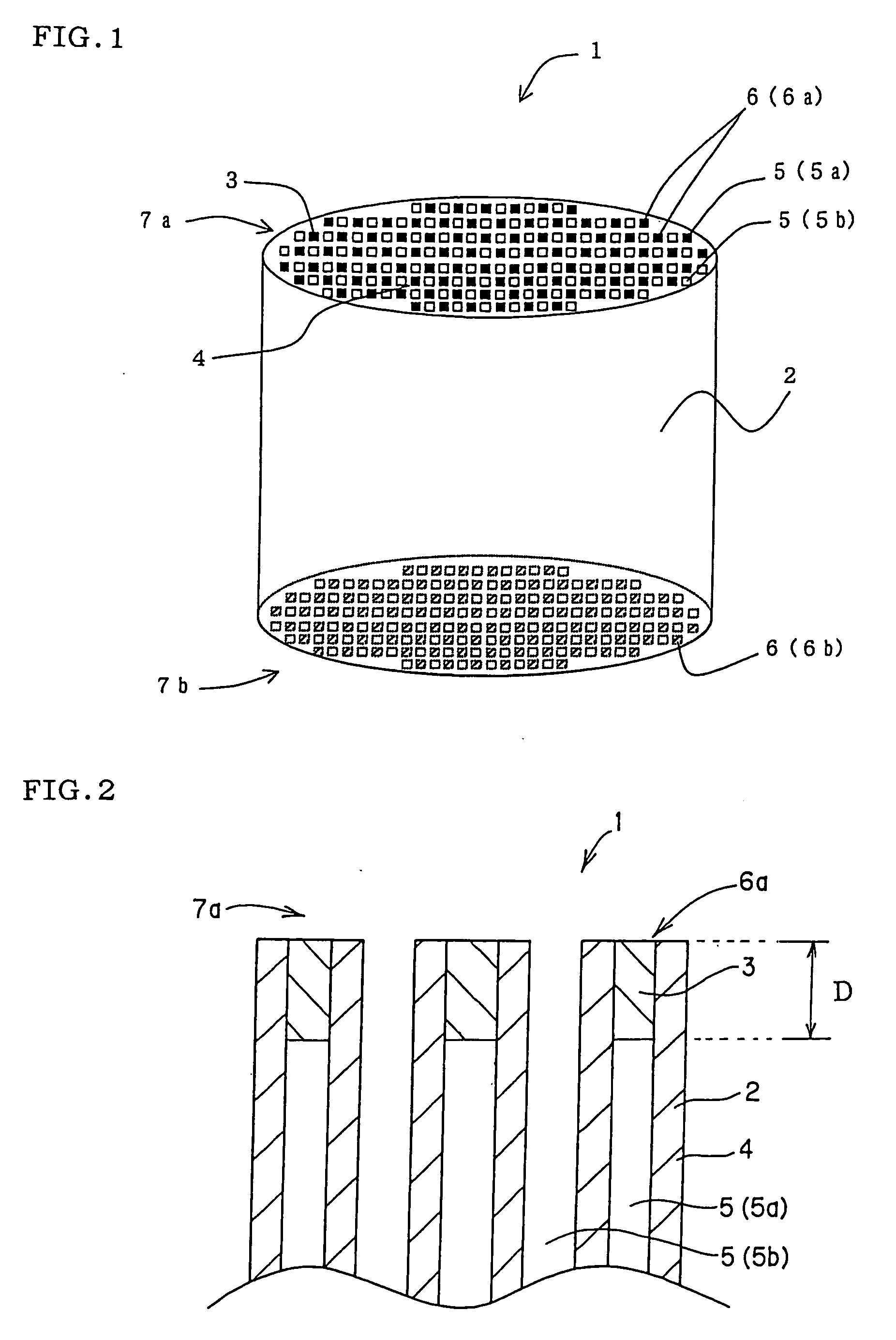
BACKGROUND OF THE INVENTION AND RELATED ART STATEMENT [0001] The present invention relates to a method for manufacturing a plugged honeycomb structure capable of easily manufacturing a plugged honeycomb structure having a uniform depth of plugging members plugging open ends of cells and a device for manufacturing plugged honeycomb structure capable of effectively manufacturing such a plugged honeycomb structure. [0002] There has been employed a ceramic plugged honeycomb structure excellent in thermal resistance and corrosion resistance as a carrier for a catalyst device or a filter used for environmental measures and recovery of specific substances. Particularly, the plugged honeycomb structure is recently in high demand as a diesel particulate filter (DPF) for trapping particulate matter (PM) discharged from a diesel engine. [0003] As shown in FIG. 9, a plugged honeycomb structure 21 is provided with plugging members 26 for plugging open ends on one side of predetermined cells 24 a...

Claims


Application Information

Patent Timeline
IPC IPC(8): C04B33/32
CPCB01D46/0001Y02T10/20B01D2279/30B28B11/006C04B35/10C04B35/185C04B35/19C04B35/195C04B35/443C04B35/478C04B35/565C04B35/584C04B38/0006C04B38/0012C04B41/009C04B41/5024C04B41/85C04B2111/00129C04B2111/00793C04B2111/0081F01N3/0222B01D46/2418C04B38/0054C04B38/0074C04B38/0645C04B37/005C04B41/53Y02T10/12
Inventor ICHIKAWA, YUKIHITOENOMOTO, AKIO
Owner NGK INSULATORS LTD
Learn More