For example, a capacitive drop off-line
LED driver from On
Semiconductor (Application Note AND8146 / D) is a non-isolated driver with low efficiency, is limited to deliver relatively low power, and at most can deliver a
constant current to the LED with no temperature compensation, no dimming arrangements, and no voltage or current protection for the LED.
In general, these various LED drivers are overly complicated, such as using
secondary side signals (feedback loops) which have to be coupled with the controller primary side, across the isolation provided by one or more transformers.
Such
current mode regulators require relatively many functional circuits while nonetheless continuing to exhibit stability problems when used in the
continuous current mode with a
duty cycle (or duty ratio) over fifty percent.
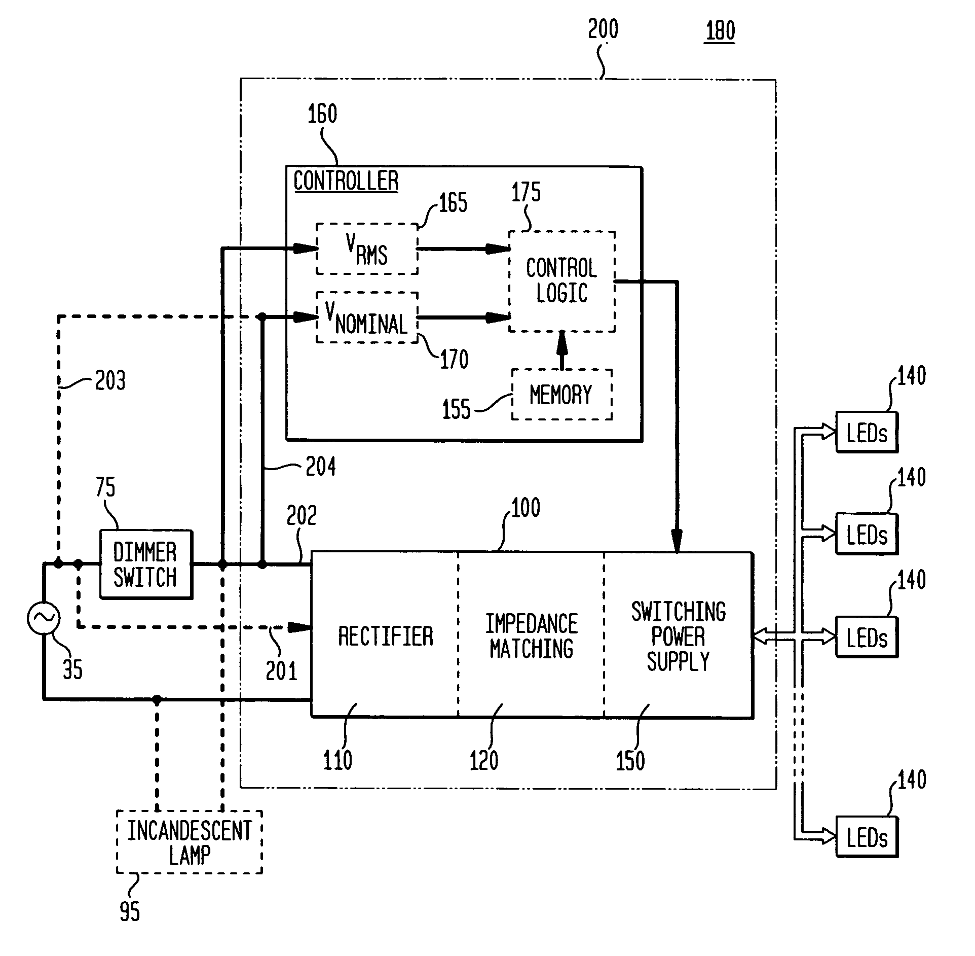
Many of these power supplies (i.e., drivers) are effectively incompatible with the existing
lighting system infrastructure, such as the lighting systems typically utilized for incandescent or fluorescent lighting.
These power supplies, generally implemented as a form of
switching power supplies, are particularly incompatible with phase-modulating “
dimmer” switches utilized to alter the brightness or intensity of light output from incandescent bulbs.
Accordingly, replacement of incandescent lamps by LEDs is facing a challenge: either do a complete rewiring of the lighting infrastructure, which is expensive and unlikely to occur, or develop new LED drivers compatible with
phase modulation of the input AC voltage by commercially available and already installed dimmers switches.
This proposal is complicated, requires excessively many components to implement, and is not particularly oriented to AC utility lighting.
When coupled with a
dimmer, however, its LED regulation is poor and it does not completely support stable operation of the dimmer in the full range of output loads, specifically when both incandescent and LED lamps are being used in parallel.
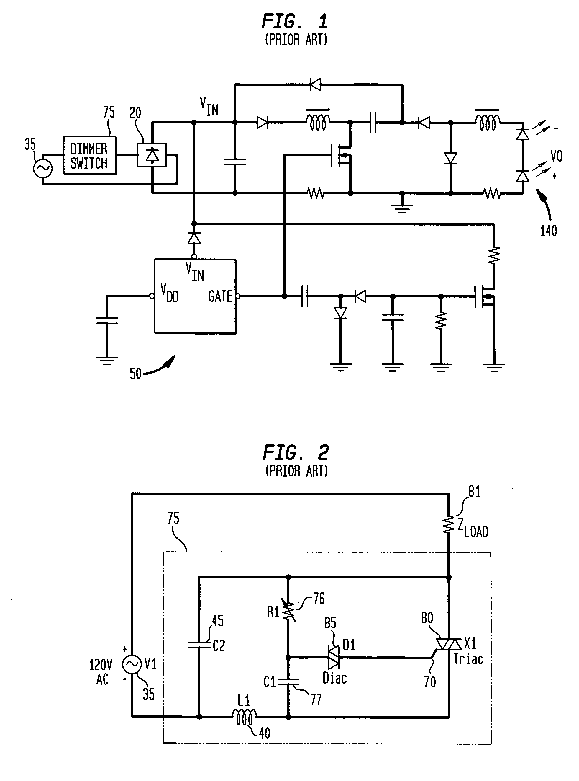
Typical prior art, off-line AC / DC
converters that drive LEDs using
phase modulation from a dimmer switch have several problems associated with providing a quality drive to LEDs, such as: (1) such
phase modulation from a dimmer switch can produce a
low frequency (about 120 Hz) in the optical output, which can be detected by a
human eye or otherwise create a reaction in people to the oscillating light; (2) filtering the input voltage may require quite a substantial value of the input
capacitor, compromising both the size of the converter and its life; (3) when the
triac 80 is turned on, a large
inrush current may be created, due to a
low impedance of the input filter, which may damage elements of both the dimmer switch 75 and any
LED driver; and (4)
power management controllers are typically not designed to operate in an environment having phase modulation of input voltage and could malfunction.
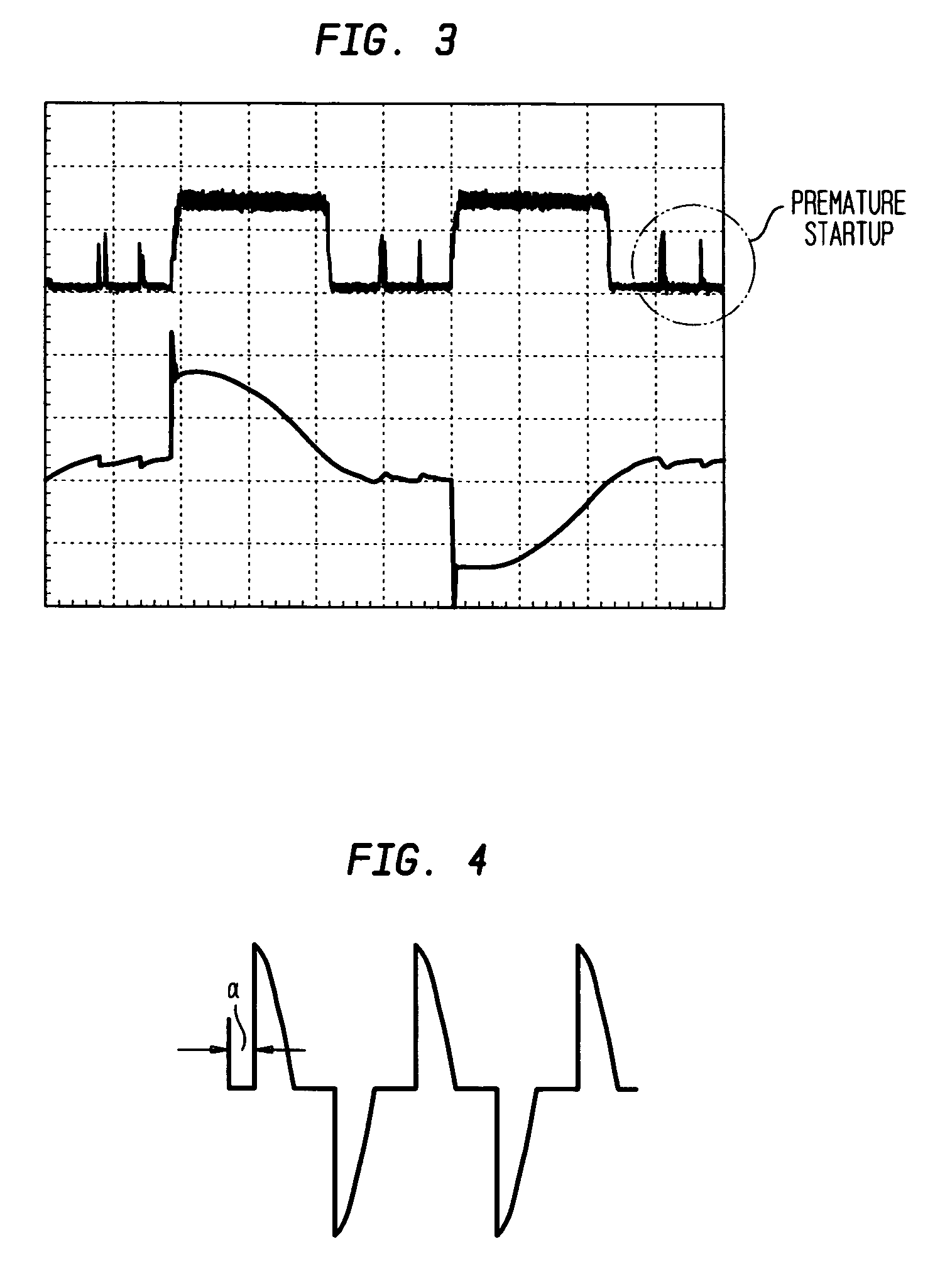
As a consequence, the small charging current may not be enough to charge C1 to the
diac 85 breakover voltage during one
half cycle.
When a dimmer switch is used with a load drawing or sinking a small amount of current, ILOAD80 will provide inconsistent behavior unsuitable for applications with LED drivers.

