
Digital double-loop output voltage regulation

Active Publication Date: 2007-08-09
BEL POWER SOLUTIONS INC +1
View PDF99 Cites 45 Cited by
  • Summary
  • Abstract
  • Description
  • Claims
  • Application Information

AI Technical Summary

Benefits of technology

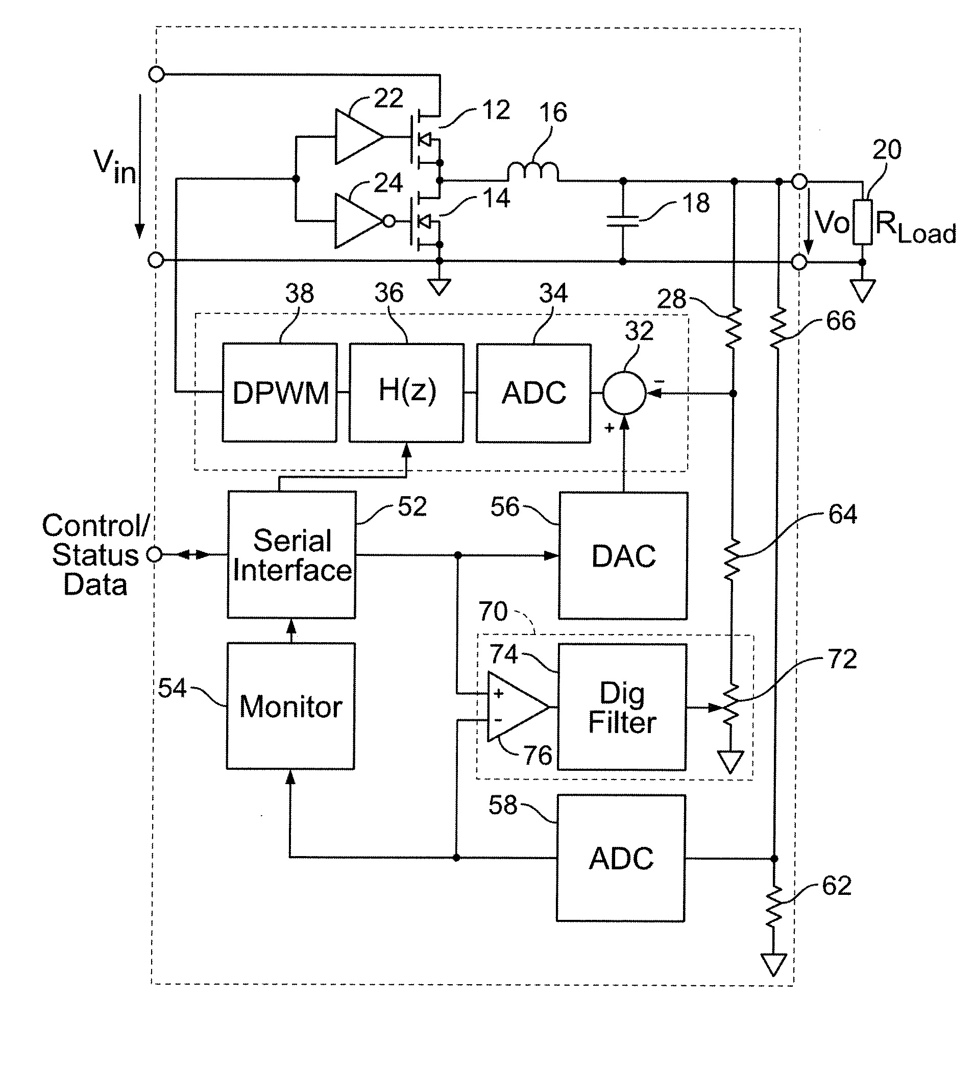
[0009] The present invention provides a switched mode voltage regulator having a digital control system. Generally, the voltage regulator comprises at least one power switch adapted to convey power between respective input and output terminals of the voltage regulator and a digital controller adapted to control operation of the power switches responsive to an output of the voltage regulator. The digital controller further comprises dual digital control loops in which a first control loop provides high speed with lower regulation accuracy and a second control loop has high accuracy with lower speed. Thus, the invention provides the advantages of both high speed and high accuracy.
[0010] More particularly, the first digital control loop includes a first analog-to-digital converter providing a first digital error signal representing a difference between a first output measurement of the voltage regulator and a reference value, a first digital filter providing a digital control output based on the first digital error signal, and a digital pulse width modulator providing a control signal to the power switches. The control signal has a pulse width corresponding to the digital control output. The second digital control loop includes a second analog-to-digital converter providing a second output measurement of the voltage regulator. The second digital control loop provides a second digital error signal representing a difference between the second output measurement and the reference value. The second analog-to-digital converter has greater resolution than the first analog-to-digital converter. The second digital error signal is applied to the first digital control loop to thereby improve accuracy of the first output measurement.

Problems solved by technology

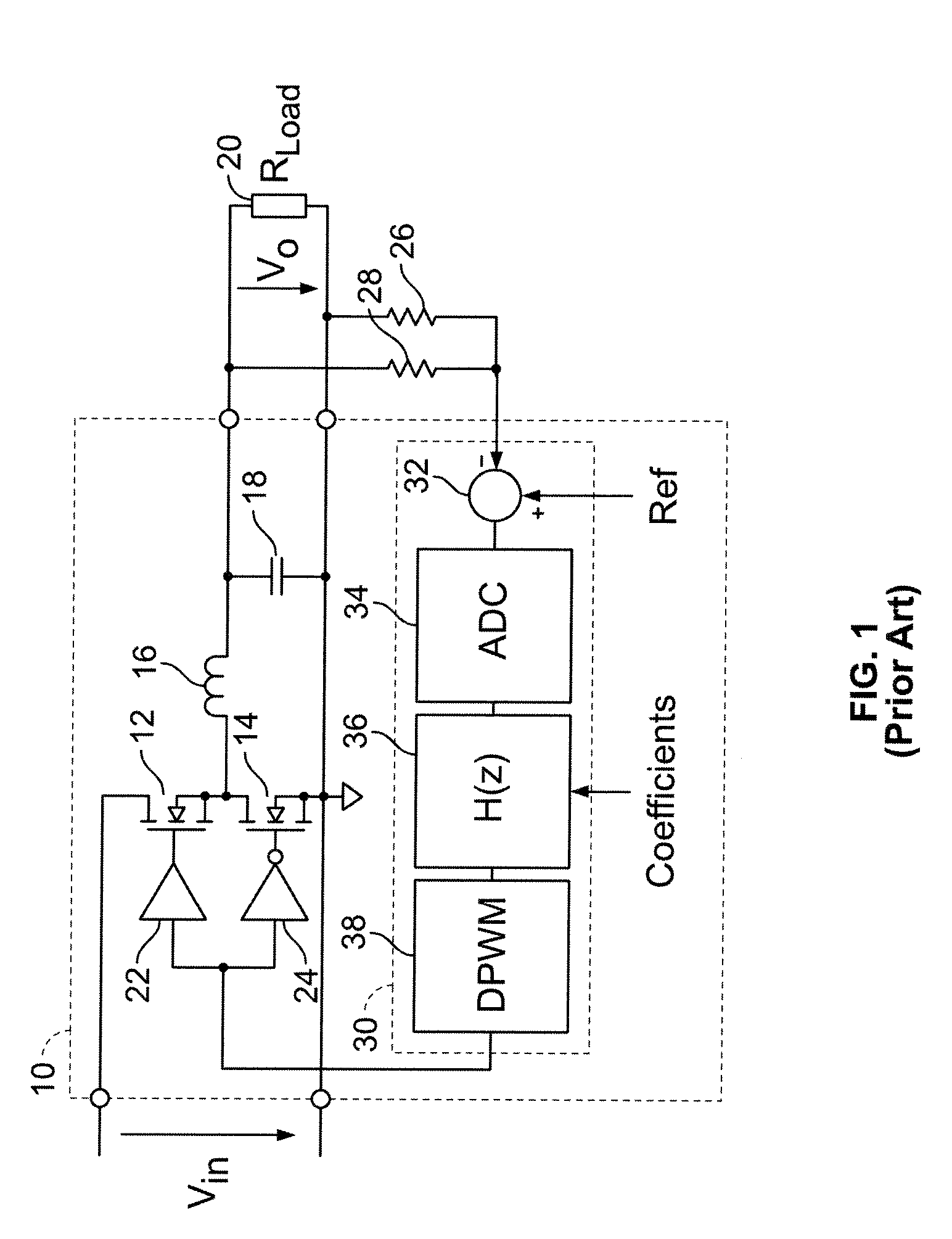
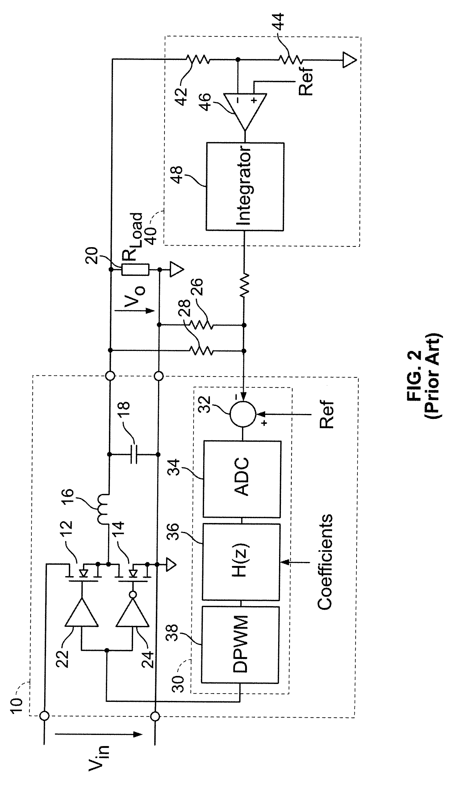
If the output voltage needs to be programmable through a large range, it is even more difficult to maintain a small DC error on the subtractor and therefore set point accuracy errors will increase.
While the circuit can be made accurate over a wide range by providing adjustable gain and offset, this comes with additional cost and complexity.
Very often, fast response time and DC precision are contradictory requirements.
The bit size of the digital signal also affects the complexity of the digital circuitry that implements the transfer function H(z) and hence the associated cost.

Method used


Image

  • Digital double-loop output voltage regulation
  • Digital double-loop output voltage regulation
  • Digital double-loop output voltage regulation

Examples


first embodiment

[0028] Referring now to FIG. 3, a switched mode voltage regulator having a digital double-loop control circuit is illustrated in accordance with the invention. The digital control circuit includes a serial interface 52 that permits bidirectional data communication with a host system to receive data to control operation of the digital control circuit, and hence the voltage regulator, and to send status information back to the host system. A digital-to-analog converter 56 is coupled to the serial interface 52. A digital reference value provided from the host system via the serial interface 52 (or retained in memory within the serial interface 52) is converted by the digital-to-analog converter 56 to a reference voltage, that is in turn provided to the subtractor 32 for comparison to the representation of the output voltage VO. This way, the host system can define the reference voltage, and thereby control the output voltage VO. The serial interface 52 also communicates filter coeffici...

second embodiment

[0035] Referring now to FIG. 5, a switched mode voltage regulator having a digital double-loop control circuit is illustrated in accordance with the invention. This embodiment differs from the preceding embodiment by including a digital filter circuit 100 having a digital comparator 102, a digital filter 104, and adder 106. As in the preceding embodiment, the digital comparator 102 compares the digital reference value provided by the host system (or retained in memory) with the digital measurement of the output voltage VO, and produces a digital error value. The digital error value passes through the digital filter 104 and provides a digital value to the adder 106. The adder combines the digital reference value with the filtered digital value to produce an adjusted digital reference value. The adjusted digital reference value is provided to digital-to-analog converter 56, which converts the digital reference value to a reference voltage that is in turn provided to the subtractor 32 ...

third embodiment

[0039] Referring now to FIG. 7, a switched mode voltage regulator having a digital double-loop control circuit is illustrated in accordance with the invention. This embodiment differs from the preceding embodiments by converting the output voltage VO directly into a digital value, instead of the error of the output voltage VO. The output voltage VO is applied directly to the analog-to-digital converter 34, which provides a digital value to a subtractor 132. As in the preceding embodiment, the digital comparator 102 receives at a first input the digital reference value provided by the host system and at a second input the digital measurement of the output voltage VO, and produces a digital error value. The digital error value passes through the digital filter 104 and provides a digital value to the adder 106. The adder 106 combines the digital reference value with the filtered digital value to produce an adjusted digital reference value. The adjusted digital reference value is provid...


PUM


Abstract

A switched mode voltage regulator has a digital control system that includes dual digital control loops. The voltage regulator comprises at least one power switch adapted to convey power between respective input and output terminals of the voltage regulator and a digital controller adapted to control operation of the power switches responsive to an output of the voltage regulator. The digital controller further comprises dual digital control loops in which a first control loop provides high speed with lower regulation accuracy and a second control loop has high accuracy with lower speed. Thus, the digital control system provides the advantages of both high speed and high regulation accuracy.

Description

RELATED APPLICATION DATA [0001] This patent application is a continuation-in-part (CIP) of application Ser. No. 11 / 605,045, filed Nov. 27, 2006, which was a continuation of application Ser. No. 11 / 084,766, filed Mar. 18, 2005, now issued as U.S. Pat. No. 7,141,956 on Nov. 28, 2006.BACKGROUND OF THE INVENTION [0002] 1. Field of the Invention [0003] The present invention relates to voltage regulator circuits, and more particularly to digital control over a switched mode voltage regulator using dual feedback loops for improved regulation. [0004] 2. Description of Related Art [0005] Switched mode voltage regulators are known in the art to convert an available direct current (DC) level voltage to another DC level voltage. A switched mode voltage regulator provides a regulated DC output voltage to a load by selectively storing energy in an output inductor coupled to the load by switching the flow of current into the output inductor. A buck converter is one particular type of switched mode...

Claims


Application Information

Patent Timeline
IPC IPC(8): G05F1/00
CPCH02M3/157
Inventor CHAPUIS, ALAINROARK, DENNIS R.
Owner BEL POWER SOLUTIONS INC
Learn More