Protective layer for CMP assisted lift-off process and method of fabrication

Inactive Publication Date: 2007-08-09
HITACHI GLOBAL STORAGE TECH NETHERLANDS BV
View PDF34 Cites 13 Cited by
  • Summary
  • Abstract
  • Description
  • Claims
  • Application Information

AI Technical Summary

Benefits of technology

[0024] It is an advantage of the present invention that the corners of the P3 pole tip are protected by the protective layer from erosion or damage.
[0025] It is a further advantage of the present invention that track width is more precisely controlled due to the protection of the P3 pole tip.
[0026] It is another advantage of the present invention that laminated

Problems solved by technology

Making reliable components of such microscopic size has been a challenge to the fabricating process arts.
This problem is made even more challenging because the P3 pole shape at the ABS is preferably not a simple rectangle, but is trapezoidal, with parallel top and bottom edges, but a bevel angle preferably of approximately 8 to 15 degrees on the side edges.
Ion milling (IM) is a process that has been long used in the manufacture and shaping of such micro-components, but here there is the difficulty of maintaining the top edge dimension while trying to cut the side bevels.
The complication in developing an IM scheme is the inability to consistently achieve a TWC process and preserve TED due to insufficient resistance of the hard mask to passivate TED.
But there are inherent difficulties in depositing a sufficient carbon film thickness to provide adequate TED protection, because as the film's thickness increases, stress may result in delamination or wafer bowing.
Thus the ability to extend the P3 carbon process to track-width dimensions below 200 nm will be increasingly problematic.
Moreover, at TWD below 200 nm, the pole piece will be fragile and removal of redeposited materials (milling nonvolatile by-products) on the top and sides of the pole tip will be increasingly more difficult.
Re

Method used


Image

  • Protective layer for CMP assisted lift-off process and method of fabrication
  • Protective layer for CMP assisted lift-off process and method of fabrication
  • Protective layer for CMP assisted lift-off process and method of fabrication

Examples


Example

[0040] To aid in the understanding of the structures involved in the present invention, the following discussion is included with reference to FIGS. 1-4.

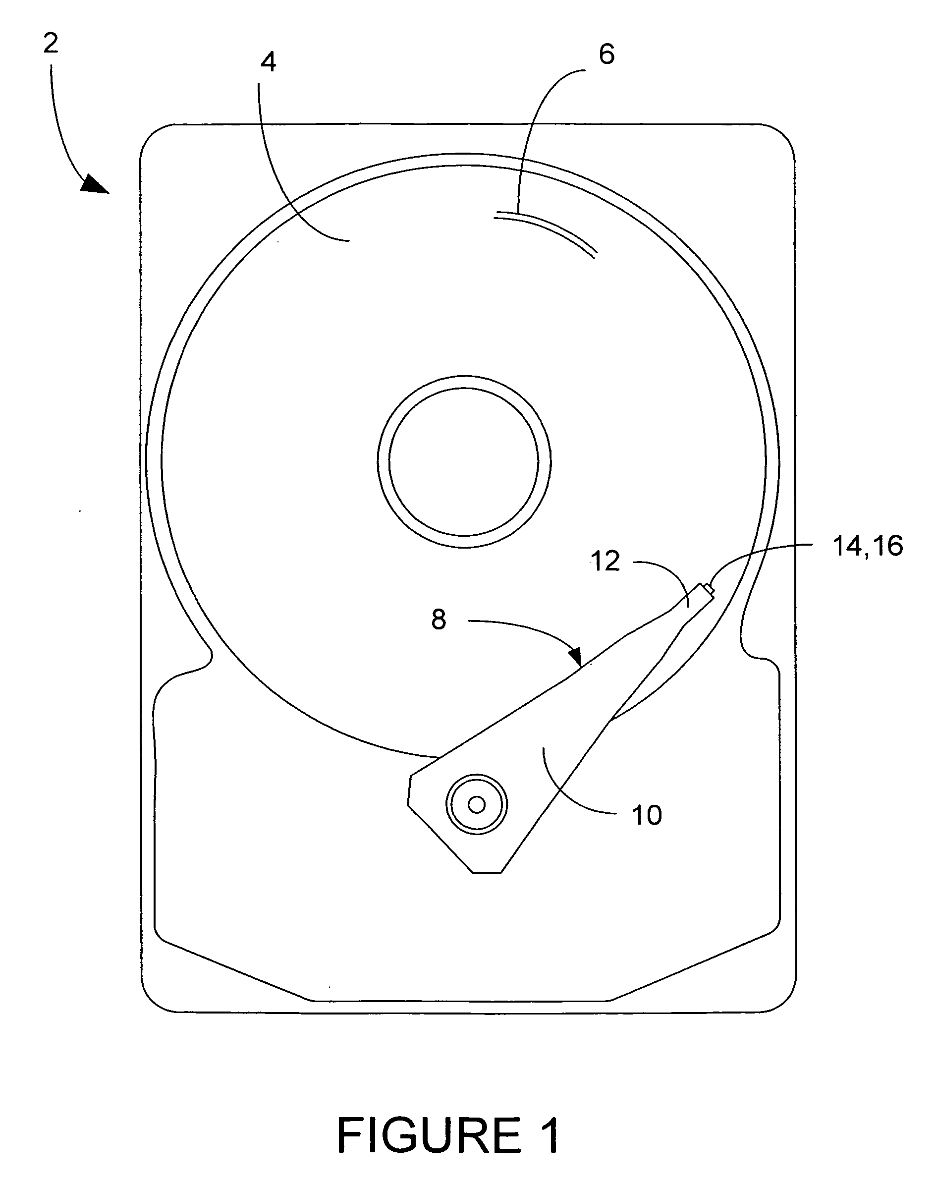
[0041] A magnetic disk drive 2 is shown generally in FIG. 1, having one or more magnetic data storage disks 4, with data tracks 6 which are written and read by a data read / write device 8. The data read / write device 8 includes an actuator arm 10, and a suspension 12 which supports one or more magnetic heads 14 included in one or more sliders 16.

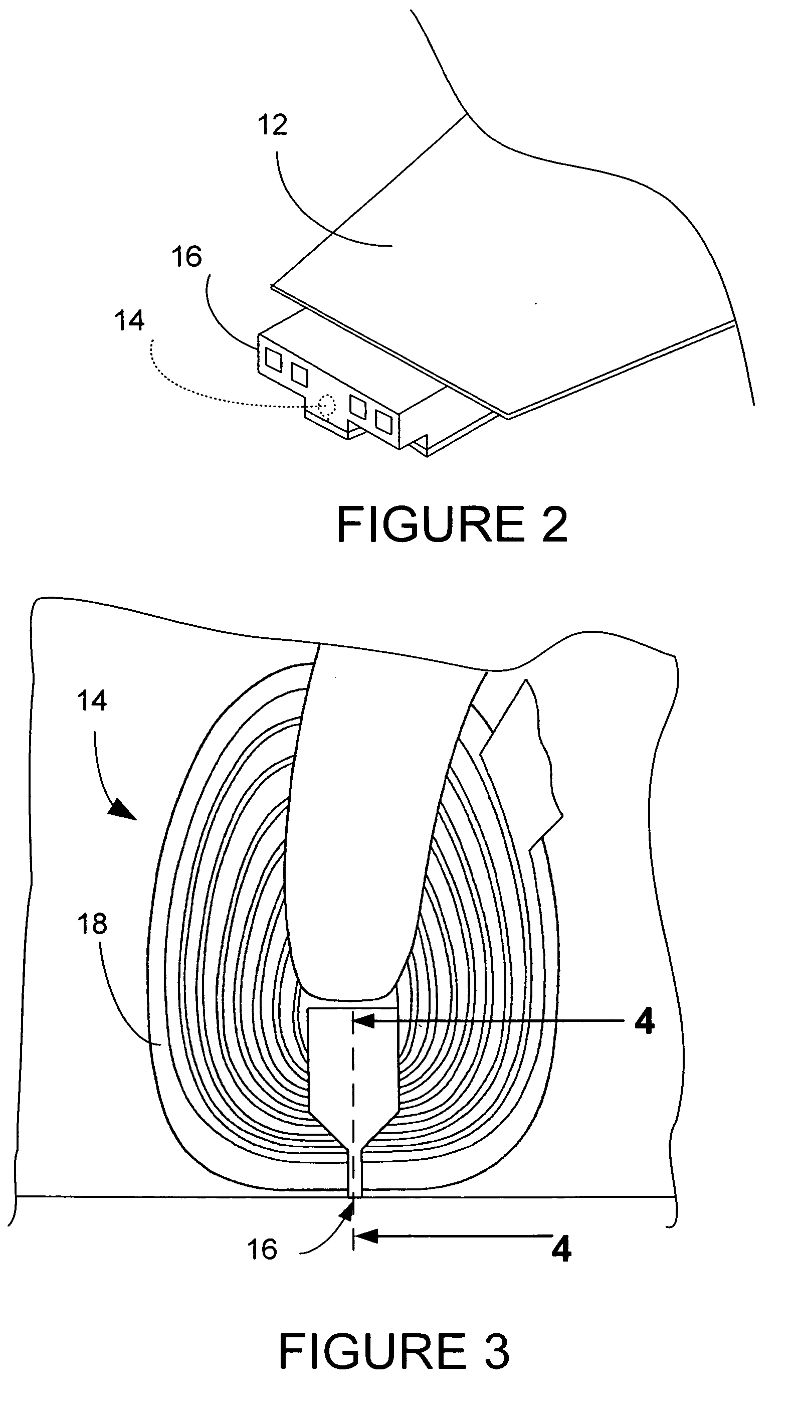
[0042]FIG. 2 shows a slider 16 in more detail being supported by suspension 12. The magnetic head 14 is shown in dashed lines, and in more detail in FIGS. 3 and 4. The magnetic head 14 includes a coil 18, and slider 16.

[0043]FIG. 4 (prior art) is a side cross-sectional diagram of the write head portion of a typical prior art perpendicular magnetic head. A slider 20 has an air bearing surface (ABS) 22 which flies above the surface of a hard disk 24. The disk 24 includes a high coercivity mag...


PUM


Abstract

A magnetic head is disclosed having a write head with an encapsulated protected pole structure, which includes a P3 pole tip. A protective layer surrounds at least a portion of the P3 pole tip, and an encapsulating material layer surrounds a portion of the protective layer. Also disclosed is a method of fabrication for a write head with an encapsulated protected pole structure.

Description

BACKGROUND OF THE INVENTION [0001] 1. Field of the Invention [0002] The present invention relates to heads for high track density perpendicular magnetic recording, and more particularly relates to fabrication of magnetic poles of such heads. [0003] 2. Description of the Prior Art [0004] Data has been conventionally stored in a thin magnetic media layer adjacent to the surface of a hard drive disk in a longitudinal mode, i.e., with the magnetic field of bits of stored information oriented generally along the direction of a circular data track, either in the same or opposite direction as that with which the disk moves relative to the transducer. [0005] More recently, perpendicular magnetic recording systems have been developed for use in computer hard disk drives. A typical perpendicular recording head includes a trailing write pole, a leading return or opposing pole magnetically coupled to the write pole, and an electrically conductive magnetizing coil surrounding the write pole. In ...

Claims


Application Information

Patent Timeline
IPC IPC(8): G11B5/147
CPCG11B5/1278G11B5/3169G11B5/3163G11B5/3116
Inventor LE, QUANGLI, JUI-LUNGZHENG, YI
Owner HITACHI GLOBAL STORAGE TECH NETHERLANDS BV
Why Eureka
Try Eureka