
Bone cement composite containing particles in a non-uniform spatial distribution and devices for implementation

a composite material and spatial distribution technology, applied in the field of bone cement, can solve the problems of natural penny crack formation, cement is subjected to cyclic load-bearing, corrosion fatigue, etc., and achieve the effects of treating or preventing a vertebral compression fracture, and reducing the volume of the cavity

Inactive Publication Date: 2007-08-09
OSSEON THERAPEUTICS
View PDF13 Cites 104 Cited by
  • Summary
  • Abstract
  • Description
  • Claims
  • Application Information

AI Technical Summary

Benefits of technology

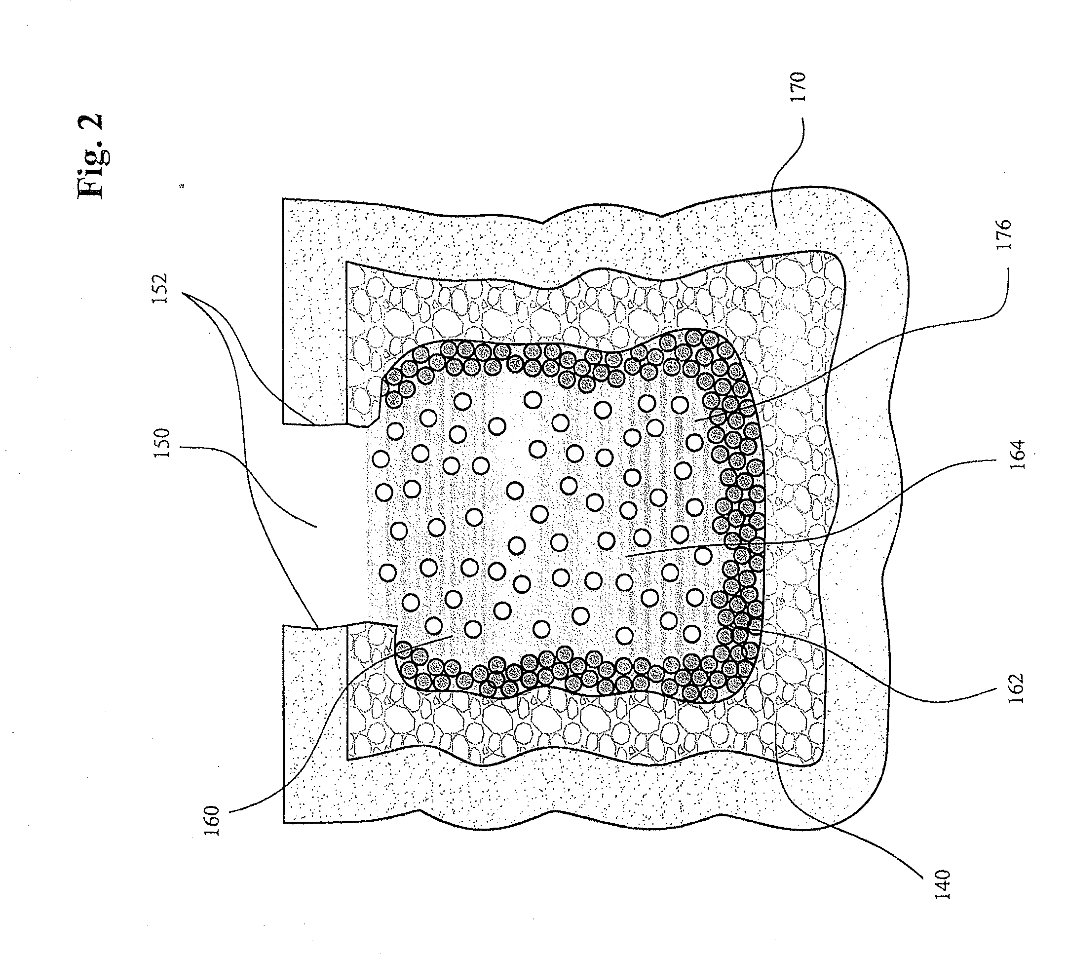
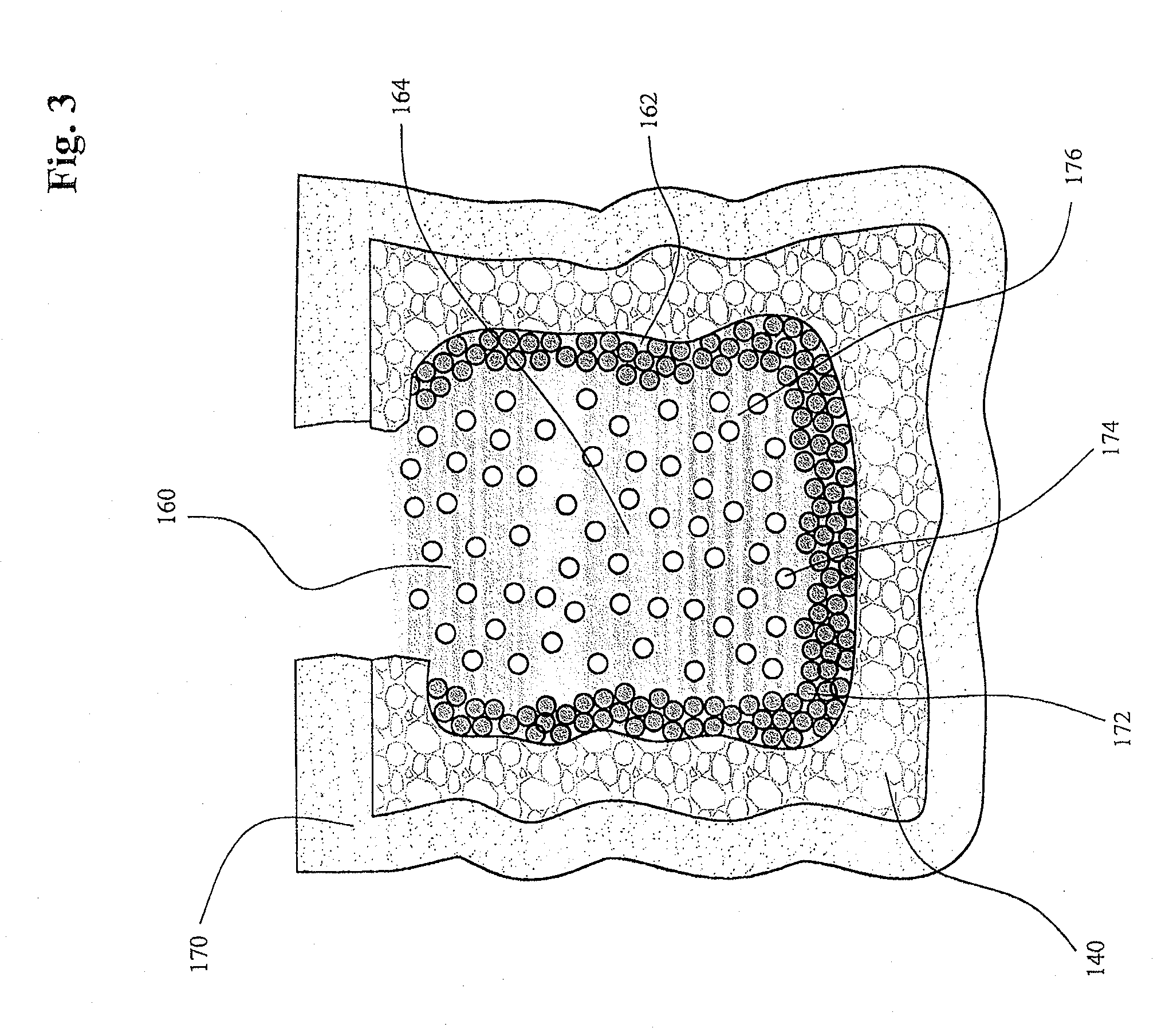
[0034] Further, disclosed is a method for treating or preventing a vertebral compression fracture. The method includes the step of inserting an insertion device percutaneously into a vertebral body. Next, the method can include the step of inserting a cavity-forming device through the insertion device into an area of cancellous bone in the vertebral body. Furthermore, the method can include the step of displacing cancellous bone with the cavity-forming device to create a cavity defined by a surface of cancellous bone. Also, the method can include the step of introducing a first media into the cavity to line at least a portion of the surface thereby reducing the volume of the cavity; and filling at least a portion of the cavity with a second media.
[0035] In another aspect, disclosed is a method for treating or preventing a vertebral compression fracture. The method can include the step of inserting an insertion device percutaneously into a vertebral body. Next, the method can include the step of inserting a cavity-forming device through the insertion device into an area of cancellous bone in the vertebral body. Next, the step of displacing cancellous bone with the cavity-forming device to create a cavity defined by a surface of cancellous bone can be performed. Further, the step of introducing a first media into the cavity to line at least a portion of the surface thereby reducing the volume of the cavity; and filling at least a portion of the cavity with a second media can also be performed. The insertion device can be a needle, which can be an eleven-gauge needle in some embodiments. The cavity-forming device can be, in some embodiments, selected from the group consisting of a mechanical tamp, a reamer, a drill, a hole puncher, and a balloon catheter. Introducing a first media into the cavity can include introducing a powder, paste, and / or suspension into the cavity.

Problems solved by technology

While this has been somewhat satisfactory, such cement is subjected to the cyclic load-bearing of daily living and, thus, to corrosion fatigue.
“Penny” cracks form naturally because the cement partially surrounding the cancellous bone matrices are crack initiators.
For this reason, implants, affixed using such bone cement, have sometimes experienced mechanical failures, after an average of 10 years, requiring another surgery, e.g., a revision repair.
The distribution of particles in the cement may have been slightly non-uniform because of the method of mixing the PMMA polymer powder with particles and the PMMA monomer in the normal doughing process, but any such non-uniformity was uncontrolled.
Such low-volume implants may fail due to another cause, that is, interfacial shear-stress failure at the bone-bone cement interface because of sparse particle-bone cement contact resulting in little or no bone ingrowth.
The probability of bone ingrowth between the bone and bone-cement interface is very likely to be low because of the small amount of cement volume utilized.

Method used


Image

  • Bone cement composite containing particles in a non-uniform spatial distribution and devices for implementation
  • Bone cement composite containing particles in a non-uniform spatial distribution and devices for implementation
  • Bone cement composite containing particles in a non-uniform spatial distribution and devices for implementation

Examples


Embodiment Construction

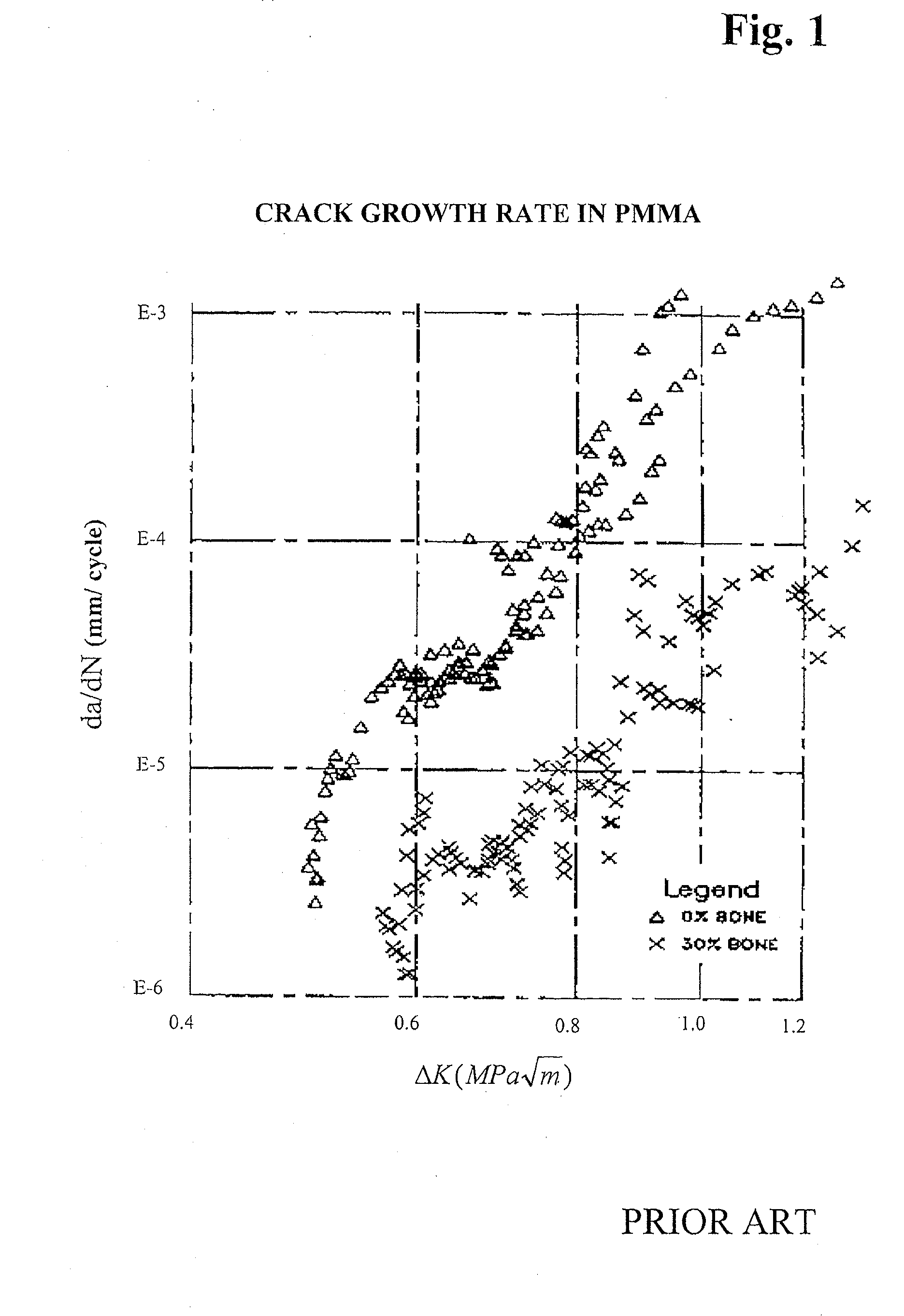
[0079] The composition regime of a composite exemplified by an optimal weight fraction of particles (which is greater than about 25%, and less than about 35% in a preferred embodiment) in the cement can be described as a crack-arresting regime. Based on the known proportion of the particles and the polymer, it can be expected that such a composite contains a substantially continuous phase of hardened acrylic cement that surrounds particles, which infrequently touch each other. It is believed that cracks, which originate in the substantially continuous polymeric phase, are only able to propagate for a short distance before they reach the hole of a particle, which then arrests the growth of the crack propagation. If a composite contains an even higher volume fraction of particles, it can exhibit another regime of behavior in vivo. In such a situation, there would again be at least some of a continuously interconnected phase of hardened acrylic cement, but, at the same time, many of th...


PUM


Abstract

One embodiment of the invention comprises a differential composite in which bone cement everywhere or substantially everywhere contains at least some non-zero volume fraction of particles, and in which the local volume fraction of particles may vary from place to place in the composite in a controlled manner. The variation may be by identifiable region or may be in the form of a gradient of the local volume fraction of particles. In at least some places, the local volume fraction of particles may be such that the particles act as crack arrestors. Close to the interface with natural bone, the local volume fraction of particles may be greater. In at least some places adjoining natural bone, the local volume fraction of particles may be such as to allow bone ingrowth into appropriate region(s) of the composite, resulting in improved interfacial shear strength. Methods and apparatuses for producing and delivering the composite are also disclosed, which may include use of an introducer and an expandable basket-type device.

Description

CROSS-REFERENCE TO RELATED APPLICATIONS [0001] This application claims priority under 35 U.S.C. § 119 to U.S. Provisional Application No. 60 / 761,454, filed Jan. 23, 2006, the disclosure of which is incorporated by reference herein in its entirety.BACKGROUND OF THE INVENTION [0002] The invention relates to bone cement, and more specifically to bone cement that contains particles for the purpose of improving its biomechanical and biomaterial properties. This invention further relates to devices and methods for its implementation, which are also disclosed herein. [0003] Bone cement has often been used as grout to provide support either for implantation of prostheses or for reduction of diseased bone. Bone cement has been widely used in artificial total joint replacements in orthopedic surgery in order to bond implants to bone. [0004] One formulation is to mix the powder and monomer of polymethylmethacrylate (PMMA) until it reaches a “dough-like” stage and then is inserted, often under ...

Claims


Application Information

Patent Timeline
IPC IPC(8): A61K6/08A61K6/884
CPCA61B17/8858A61L27/44A61L24/0073A61L24/0005A61L2430/02
Inventor LIU, Y. KINGLAU, JAN R.STALCUP, JOHNLYSTER, MICHAEL T.
Owner OSSEON THERAPEUTICS
Learn More