Airfoil for a helicoptor rotor blade

Active Publication Date: 2007-08-16
SIKORSKY AIRCRAFT CORP
View PDF20 Cites 57 Cited by
  • Summary
  • Abstract
  • Description
  • Claims
  • Application Information

AI Technical Summary

Benefits of technology

[0009] The airfoil includes a reduced thickness and camber of the leading edge region (x/c≦0.3) which delays the formation of shock waves at high Mach number/low lift coefficient and moderate Mach number/high lift coefficient conditions. This results in improvements in maximum lift

Problems solved by technology

Among these is the tendency of the retreating blade to stall at high forward airspeeds.
As the forward airspeed increases, the airflow velocity across the retreating blade slows such that the blade may approach a stall condition.
This dissymmetry may create an unstable condition if lift is not equalized across the advancing and retreating sides of the rotor.
That is, the requirements on an airfoil section at higher speeds are generally more complex than those for a fixed wing aircraft because, on a single revolution of the rotor blade, an airfoil section thereof experiences lift coefficients from negative values to positive value with section Mach numbers from subsonic to transonic values.
When a significant part of the rotor blade is operating beyond the maximum lift coefficient of the local airfoil se

Method used


Image

  • Airfoil for a helicoptor rotor blade
  • Airfoil for a helicoptor rotor blade
  • Airfoil for a helicoptor rotor blade

Examples


Embodiment Construction

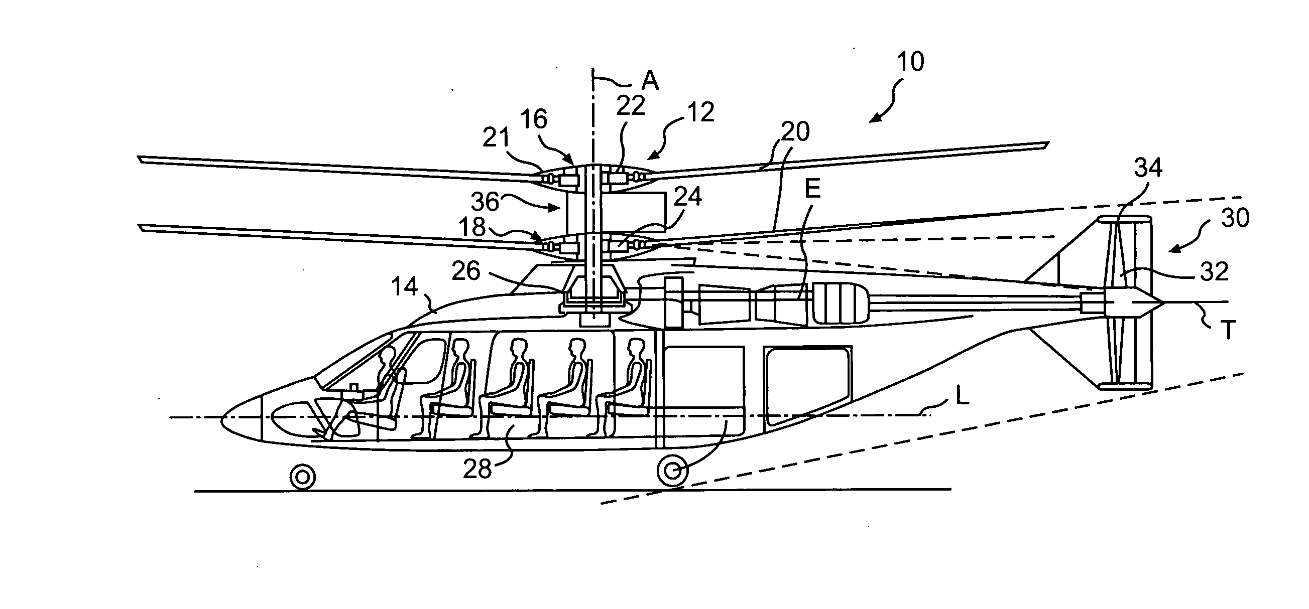
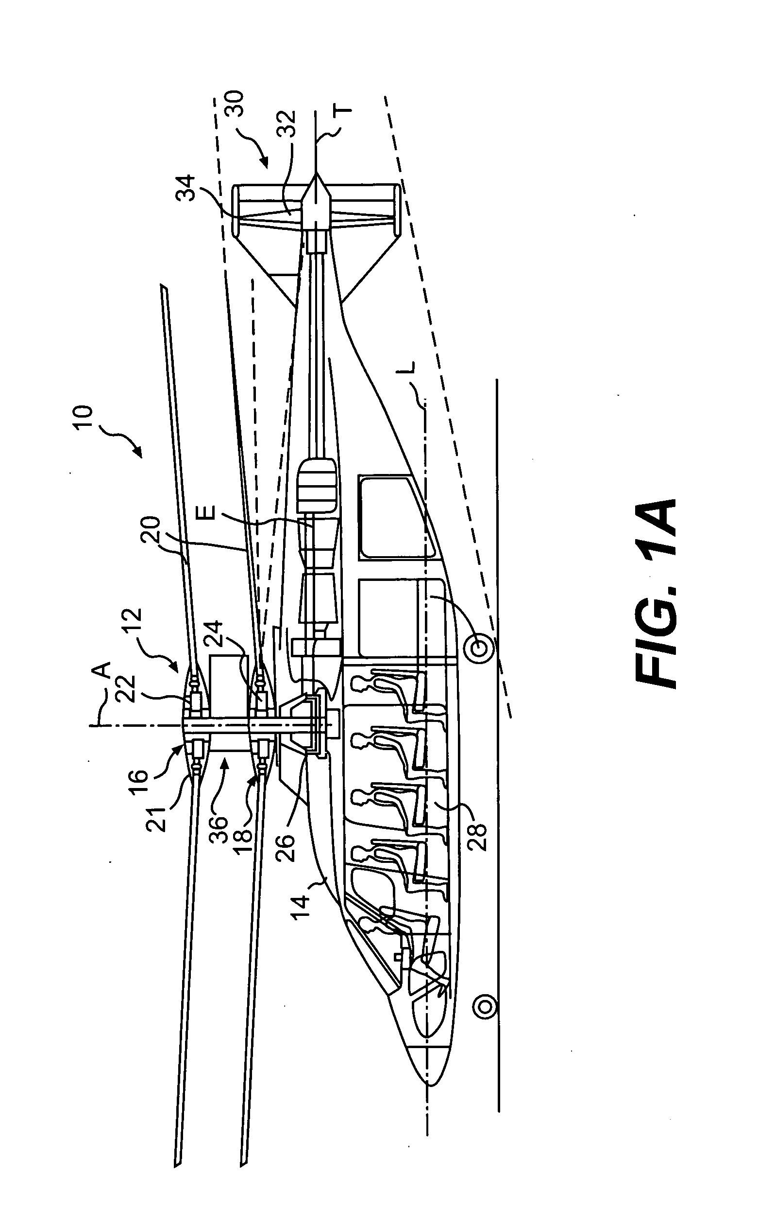
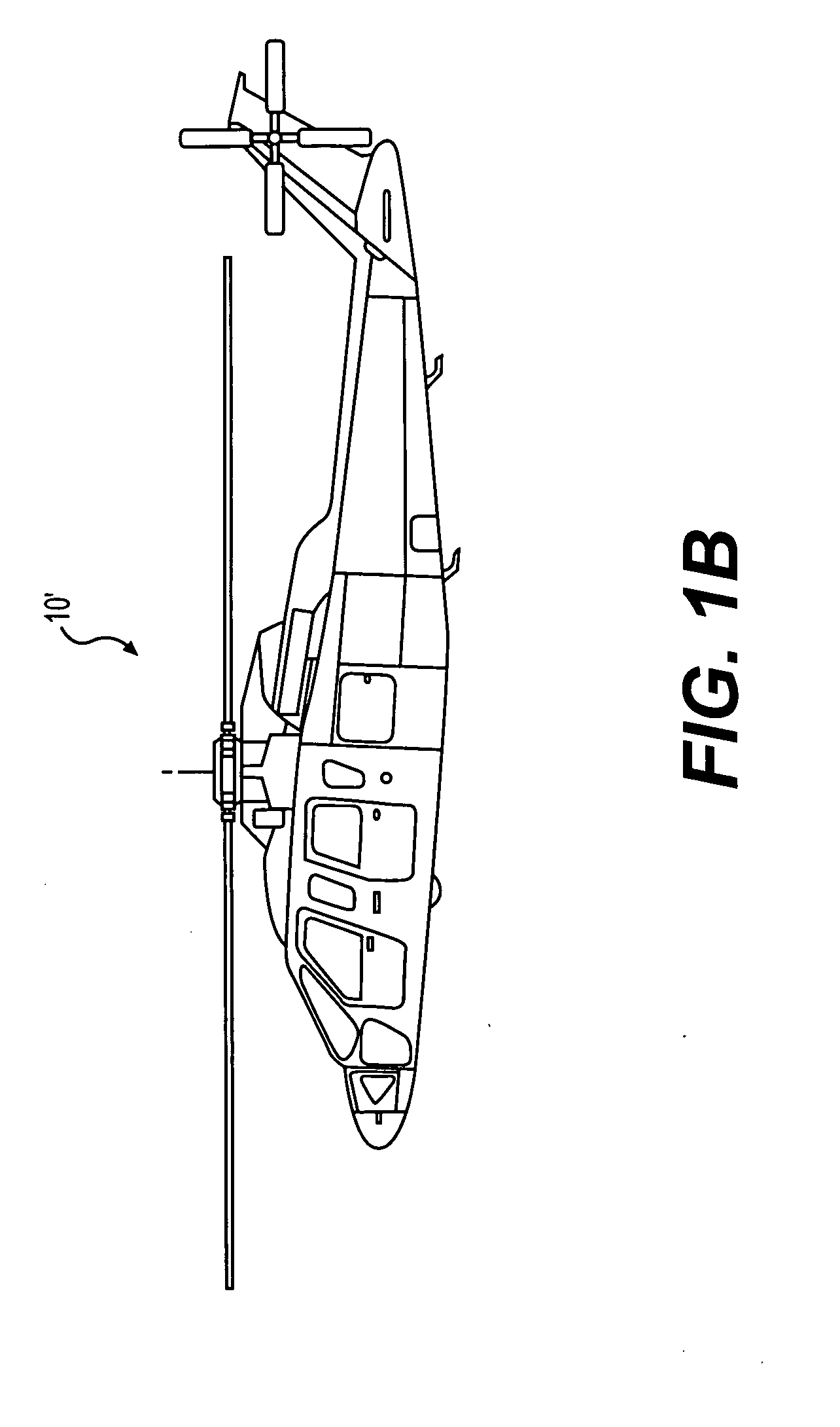
[0029]FIG. 1A illustrates an exemplary high speed compound rotary-wing aircraft 10 having a dual, contra-rotating, coaxial rotor system. 12. The aircraft 10 includes an airframe 14 that supports the rotor system 12 as well as a propulsive system 30 which provides translational thrust generally parallel to an aircraft longitudinal axis L. Although a particular aircraft configuration is illustrated in the disclosed embodiment, other helicopter configurations such as tandem rotors, as well as more conventional single rotor helicopters (FIG. 1B) will also benefit from the present invention.

[0030] By way of background information, a high speed compound rotary-wing aircraft with a dual, contra-rotating, coaxial rotor system as shown in FIG. 1 is capable of higher speeds compared to conventional single rotor helicopters due in part to the balance of lift between the advancing sides of the main rotor blades on the upper and lower rotor systems. In addition, the retreating sides of the roto...


PUM

PropertyMeasurementUnit
Fractionaaaaaaaaaa
Fractionaaaaaaaaaa
Fractionaaaaaaaaaa

Abstract

An airfoil family for a helicopter rotor blade, designated SC362XX. SC362XX essentially removes the large lower surface suction peak associated with ‘drag creep’ at moderate lift coefficients while reducing the peak Mach number and shock strength at high lift/Mach number conditions. Another optional airfoil family for use at inboard regions of the helicopter rotor, which is designated SC3252XX airfoil family, is a relatively thicker airfoil section that includes a significant increase in thickness forward of the 30% x/c location to provide a relatively thick and rigid inboard section. The lift coefficient at which the drag divergence Mach number was optimized is the same in both families thereby readily providing application to a single rotor blade.

Description

BACKGROUND OF THE INVENTION [0001] The present invention is directed to an improved airfoil for use with a helicopter rotor and more particularly to an airfoil section for at least partial use on a main rotor blade of a helicopter rotor. [0002] Conventional rotary-wing aircraft have a forward airspeed limited by a number of factors. Among these is the tendency of the retreating blade to stall at high forward airspeeds. As the forward airspeed increases, the airflow velocity across the retreating blade slows such that the blade may approach a stall condition. In contrast, the airflow velocity across the advancing blade increases with increasing forward speed. Forward movement of the aircraft thereby generates a dissymmetry of lift between the advancing and retreating sides of the rotor. This dissymmetry may create an unstable condition if lift is not equalized across the advancing and retreating sides of the rotor. [0003] At higher speeds, such as, at the outer tip regions of convent...

Claims


Application Information

Patent Timeline
IPC IPC(8): B64C27/08
CPCB64C3/14Y10T29/49332Y02T50/12B64C27/467Y02T50/10
Inventor OWEN, STEPHEN J.
Owner SIKORSKY AIRCRAFT CORP
Why Eureka
Try Eureka