Autofocus control method, autofocus control apparatus and image processing apparatus

a technology of autofocus control and image processing apparatus, applied in the direction of instruments, material analysis through optical means, optical elements, etc., can solve the problems of inability to stably find the optimal focus position, limited type of optical material to be used in optical paths, etc., and achieve the effect of stably performing highly accurate autofocus control

Inactive Publication Date: 2007-08-16
SONY CORP
View PDF1 Cites 39 Cited by
  • Summary
  • Abstract
  • Description
  • Claims
  • Application Information

AI Technical Summary

Benefits of technology

[0017] According to the present embodiment, since it is possible to stably perform highly accurate autofocus control by eliminating influences due to optical systems, it is possible to realize sample ob

Problems solved by technology

However, there is the problem that the kind of optical material such as a lens to be used in an optical path is limited by the short-wavelength construction of the illumination light source, and an influence such as a speckle occurs du

Method used


Image

  • Autofocus control method, autofocus control apparatus and image processing apparatus
  • Autofocus control method, autofocus control apparatus and image processing apparatus
  • Autofocus control method, autofocus control apparatus and image processing apparatus

Examples


first embodiment

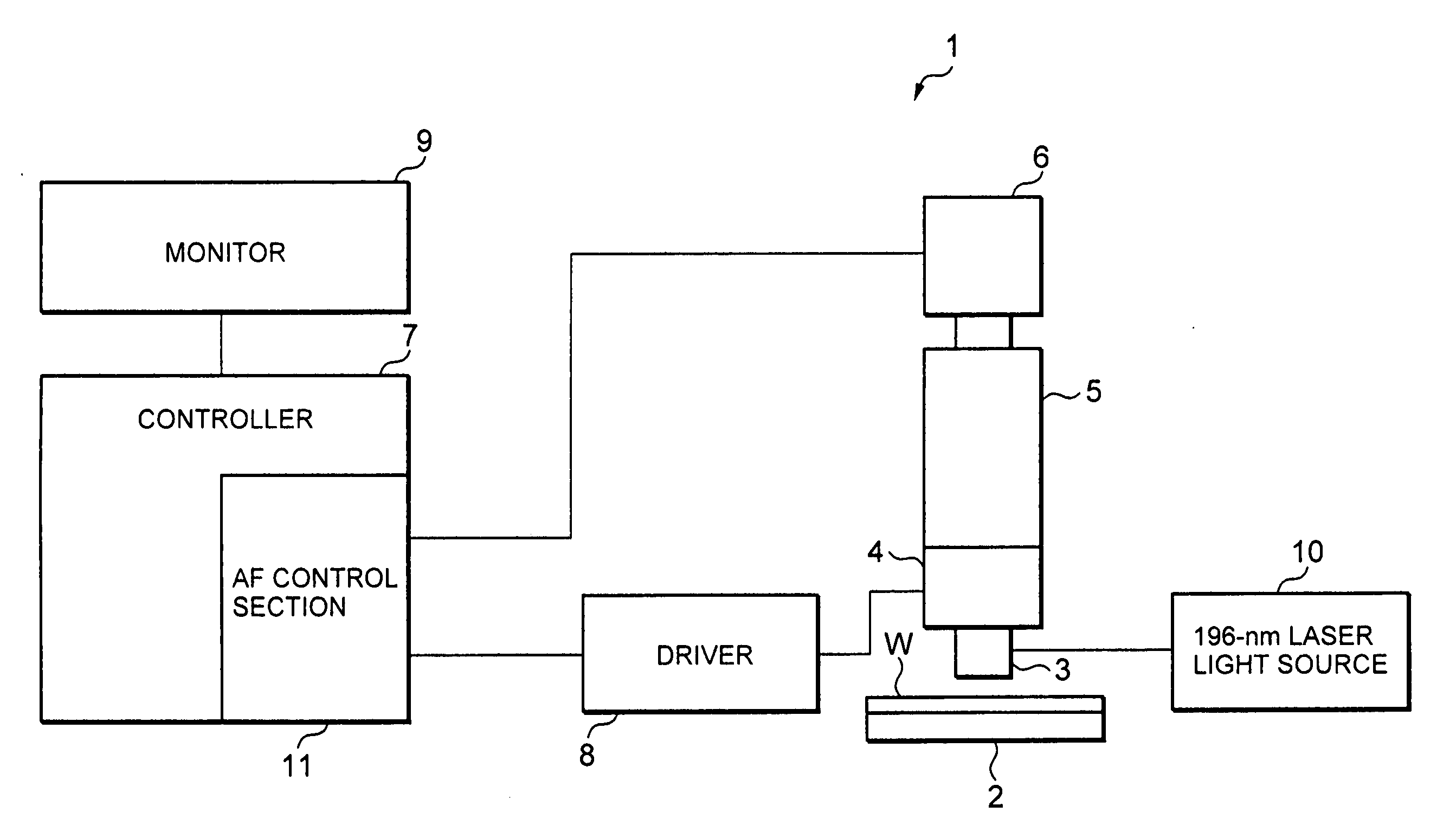
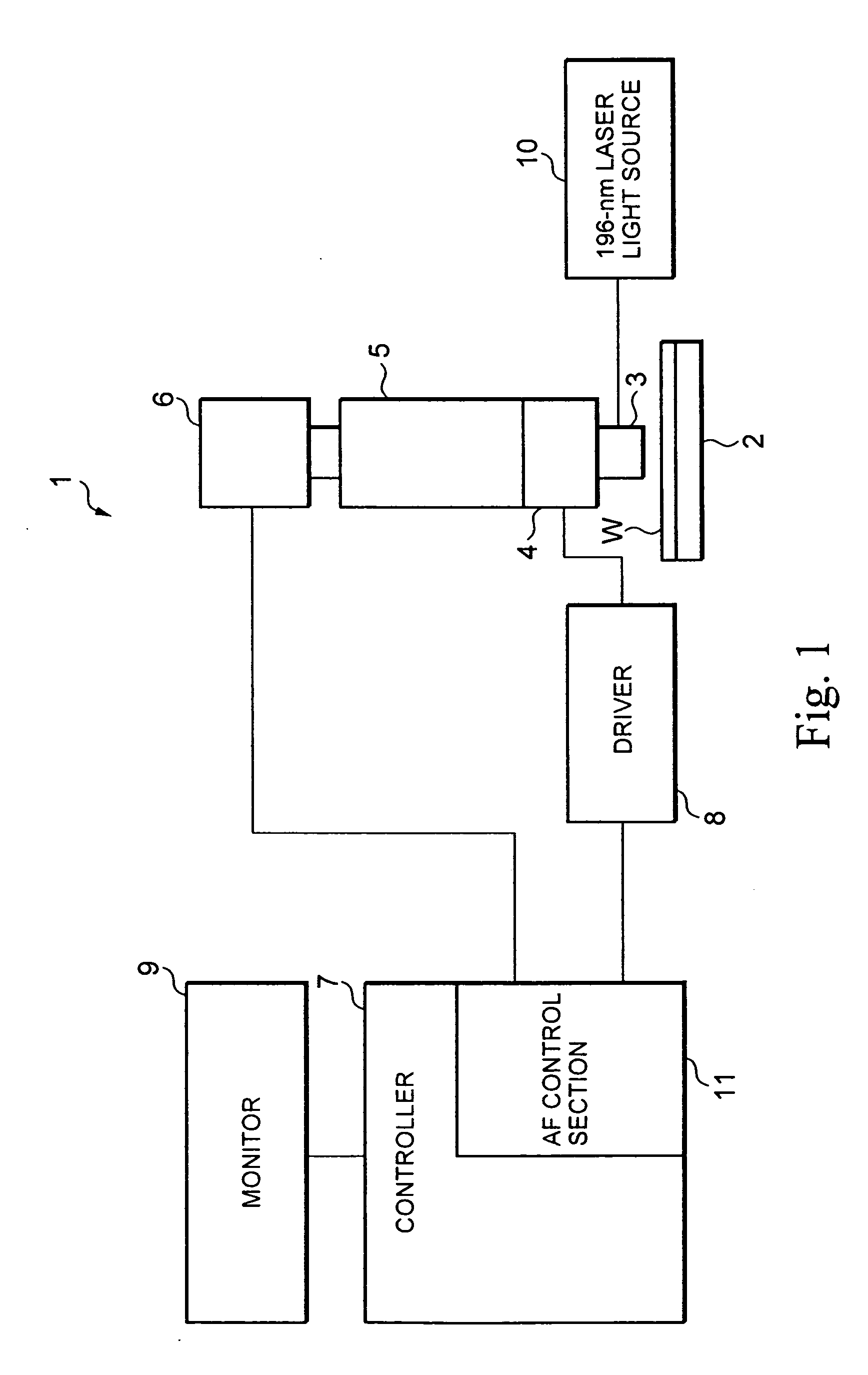
[0041]FIG. 1 is a schematic construction view of an image processing apparatus to which an autofocus control method and an autofocus control apparatus according to an embodiment of the present invention are applied. An image processing apparatus 1 is employed for surface observation of a subject sample (work), and is specifically constructed as a microscope to be employed for defect inspection of a device structure, such as a semiconductor wafer, which is constructed by micromachining being applied to its surface.

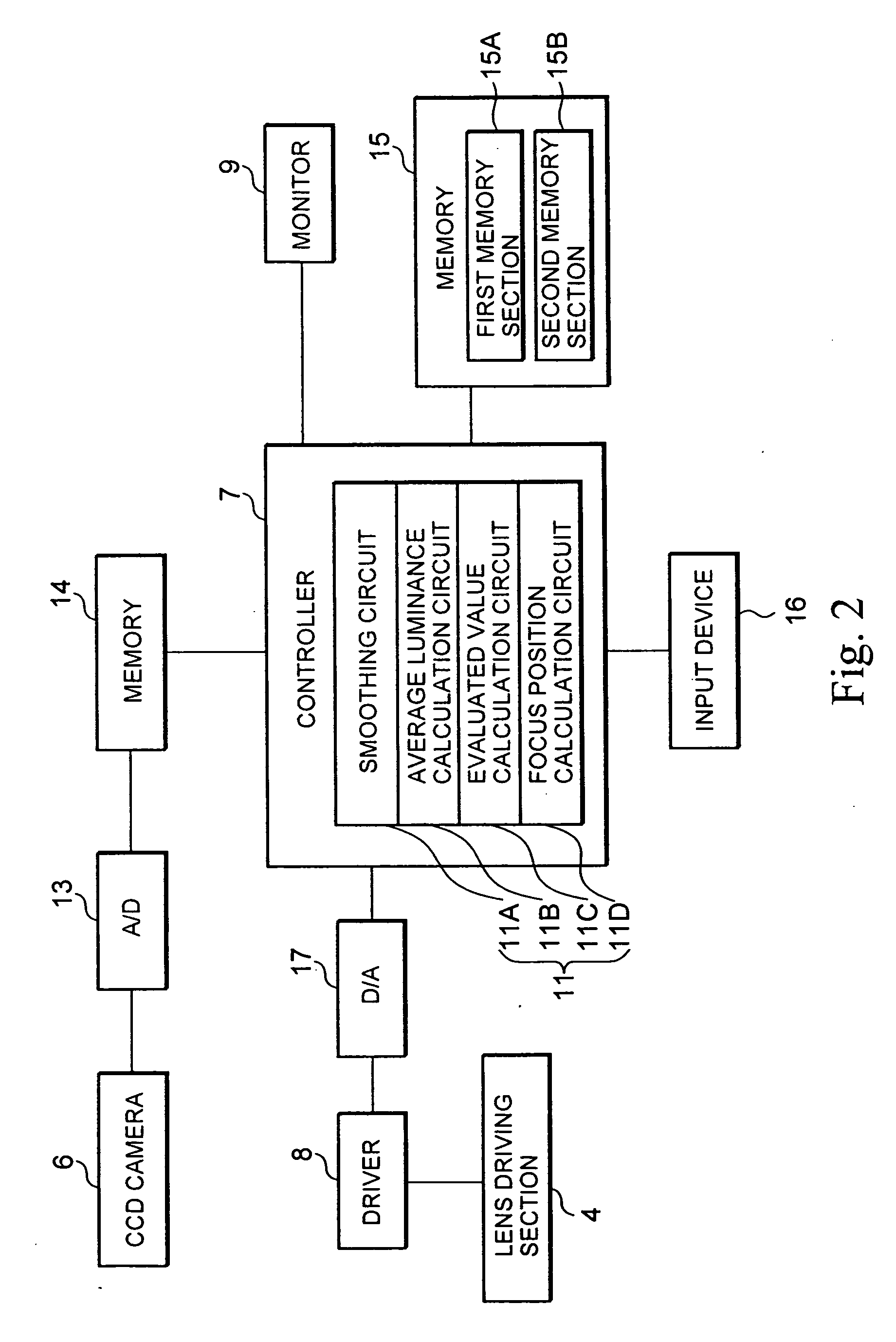
[0042] The image processing apparatus 1 is equipped with a measurement stage 2, an objective lens 3, a lens driving section 4, a lens barrel 5, a CCD (Charge Coupled Device) camera 6, a controller 7, a driver 8, a monitor 9 and an illumination light source 10.

[0043] The measurement stage 2 is constructed to support a subject sample (for example, a semiconductor wafer) W and move in the X-Y directions (in FIG. 1, in the right and left directions and in directions perpendic...

second embodiment

[0097] A second embodiment of the present invention will be described below.

[0098] As the miniaturization of minimum pattern widths (process rules) proceeds, recent semiconductor wafers are beginning to assume more three-dimensional structures in their height directions. Light sources having shorter wavelengths need shallower depth of focus and have a disadvantageous tendency to decrease the number of focusable sections of an object having a great difference of height. If a difference of height exits in a screen and different surfaces are focusable at different heights, it is necessary to perform an active focusing operation which can determine “where to be focused on”, for example, which of the surfaces of a sample is to be used as a reference surface. However, a conventional autofocus control method of finding an optimum focused position from focus evaluated values has the disadvantage of being unable to bring a desired section into focus.

[0099] To cope with this problem, a meth...

third embodiment

[0110] A third embodiment of the present invention will be described below. In the description of the present embodiment, reference will be made to a method of synthesizing an omnifocal image of a subject sample from acquired image data by applying an autofocus control method according to the present invention.

[0111] In the case of a normal optical system, if a three-dimensional object exceeding the depth of focus of the optical system is viewed therethrough, a globally focused image cannot be viewed, so that the purpose of inspection or observation cannot be satisfied. Attempts to solve this problem are made by using a method of obtaining a globally focused omnifocal image by using a special optical system such as a confocal optical system and a method of obtaining a globally focused image from images of different angles on the basis of trigonometry, but neither of these methods can be inexpensively realized, because special optical systems need to be employed.

[0112] On the other...


PUM


Abstract

An autofocus control method, an autofocus control apparatus and an image processing apparatus all of which can realize stable autofocus control operation by eliminating influences due to optical systems. In calculation of a focus evaluated value of each of sample images respectively acquired at a plurality of focused positions, each of the acquired sample image is subjected to smoothing to reduce a grayscale pattern of brightness due to an optical system, and the focus evaluated value is calculated on the basis of the smoothed sample image. In addition, the focus evaluated value is standardized with the screen average luminance of the sample image, thereby effecting optimization of the evaluated value.

Description

TECHNICAL FIELD [0001] The present invention relates to, for example, an autofocus control method, an autofocus control apparatus and an image processing apparatus all of which are suitably used in equipment for image capture, observation and inspection of a subject sample through a video camera and are capable of realizing stable autofocus operation by eliminating the influences of optical systems in particular. BACKGROUND ART [0002] Image autofocus control has heretofore been performed with focus evaluated values obtained by evaluating and quantifying the extent of focusing from image data of a subject sample (work). Namely, image data of a sample are collected at varied distances between a lens and a subject, and focus evaluated values are calculated as to the respective image data to search for a suitable focused position. [0003]FIG. 21 shows the relationship between lens-to-work distances (the horizontal axis) and focus evaluated values (the vertical axis). This relationship is...

Claims


Application Information

Patent Timeline
IPC IPC(8): G02B27/40
CPCG02B7/36G03F9/7092G03F9/7026
Inventor EBE, HIROKIYAMAUCHI, MASAYAKIKUCHI, KIYOYUKIKURODA, KIYOTAKATAKAHASI, JUNICHI
Owner SONY CORP
Why Eureka
Try Eureka