Refractive lens array for scanner application that reduces lateral tolerance sensitivity

Inactive Publication Date: 2007-08-16
AGILENT TECH INC
View PDF3 Cites 4 Cited by
  • Summary
  • Abstract
  • Description
  • Claims
  • Application Information

AI Technical Summary

Benefits of technology

[0004] In accordance with the invention, the longitudinal distance between the object plane and image plane is

Problems solved by technology

Such large angles of incidence give rise to parallax, which causes feature

Method used


Image

  • Refractive lens array for scanner application that reduces lateral tolerance sensitivity
  • Refractive lens array for scanner application that reduces lateral tolerance sensitivity
  • Refractive lens array for scanner application that reduces lateral tolerance sensitivity

Examples


Example

[0011] Reference will now be made in detail to the present embodiments in accordance with the invention, examples of which are illustrated in the accompanying drawings, wherein like reference numerals refer to the like elements throughout. The embodiments are described below in order to explain the present invention by referring to the figures.

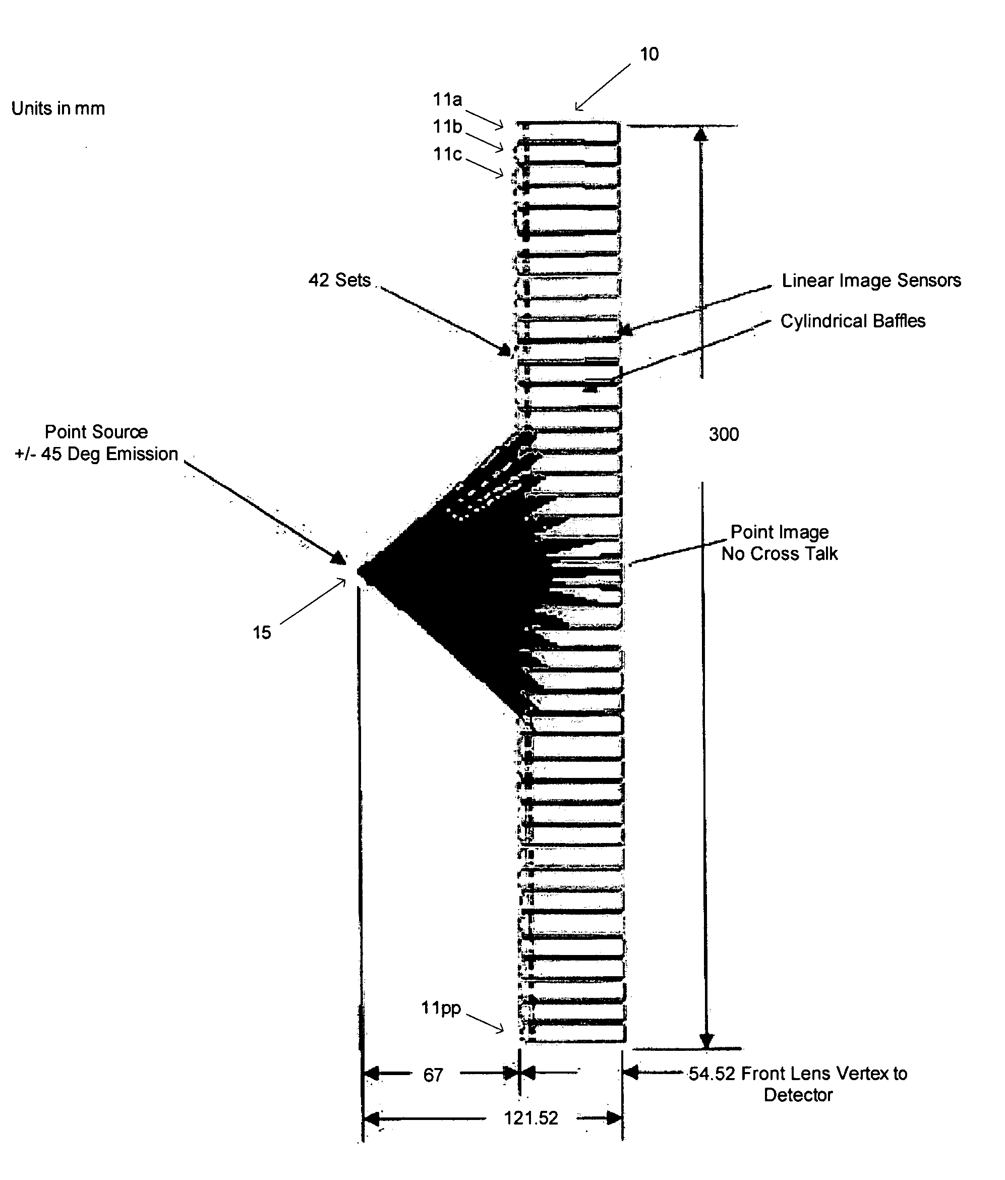
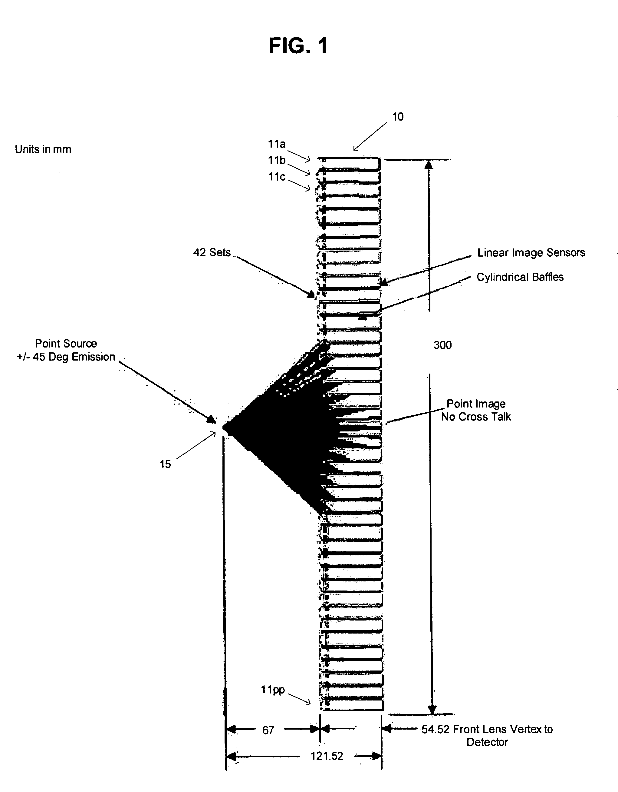
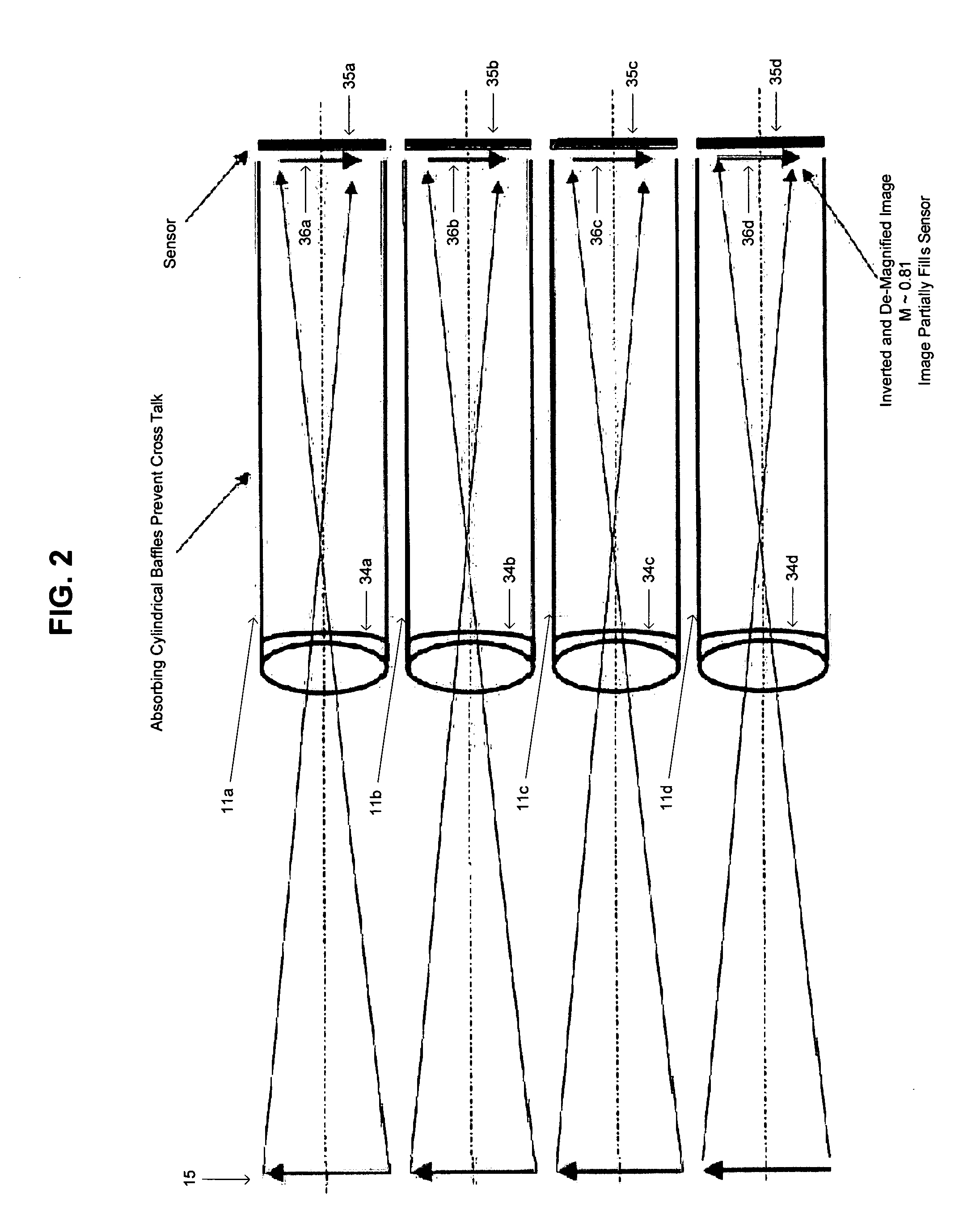
[0012]FIG. 1 is a schematic diagram of a device for imaging an object plane into a linear sensor array using a single lens array assembly 10. Referring to FIG. 1, the apparatus includes a plurality of tube-like baffles 11a through 11pp each housing an appropriately designed lens and image sensor. The lenses are arranged to provide inverted and de-magnified imaging of an object 15 to a plane of image segments.

[0013] The object distance can be altered according to the needs of the particular application. Automatic optical inspection systems used to line scan printed circuit boards need at least 40 mm between the object surface and the imaging ...


PUM


Abstract

A low cost single lens array for use in an automatic optical inspection system, so as to reduce parallax, cross talk, and sensitivity to lateral fabrication errors, and a method for stitching together image segments formed by the array. The lens array comprises a plurality of tube-like baffles, within which are disposed single lens sets and linear image sensors. These baffles are typically arranged to provide de-magnified and inverted image segments that are stitched together to provide the entire image of the surface object.

Description

BACKGROUND OF THE INVENTION 1. Description of the Related Art [0001] Automatic optical inspection systems enable the efficient and cost effective monitoring of printed circuit boards during manufacture. Large circuit board formats and high throughput common in today's low cost manufacturing environment suggest the use of optical line scan systems. Good imaging over large fields is crucial for the operation of such line scan systems. [0002] The use of linear sensor arrays such as contact image sensors (CIS) is known in the technically different fields of flatbed scanners and photocopiers. Here the surface being inspected is flat such as a piece of paper or photograph, not a printed circuit board, which has components of varying heights. Furthermore, current CIS imaging systems are designed for working at very close distances from the target surface. This is in contrast to the needs of an automated optical inspection system where the surface under test must be in the order of 30 mm-40...

Claims


Application Information

Patent Timeline
IPC IPC(8): G02B3/00
CPCB41J2/451G02B3/005G02B3/0006
Inventor GRUHLKE, RUSSELL W.GAO, WEN-LIANGDOHERTY, JOHN
Owner AGILENT TECH INC
Why Eureka
Try Eureka