System and Method for Measurement While Drilling Telemetry

a technology of telemetry and measurement, applied in the field of drilling fluid telemetry system, can solve the problems of loss of drilling time and source of noise in detected signals, and achieve the effect of removing distortion

Inactive Publication Date: 2007-08-16
BAKER HUGHES INC
View PDF9 Cites 65 Cited by
  • Summary
  • Abstract
  • Description
  • Claims
  • Application Information

AI Technical Summary

Benefits of technology

[0009]In one aspect of the present invention, a system for transmitting information in a well comprises a tubular string disposed in the well and having a drilling fluid flowing therethrough. In one aspect, a pulser is disposed in the tubular string and transmits a pulse synchronization marker comprising a chirp signal. A surface controller, acting under programmed instructions, detects the chirp signal and adjusts a signal decoding technique based on the detected chirp signal. The surface controller performs the function of noise cancellation in which noise, including at least a portion of the pump noise, is removed. The controller estimates a channel transfer function characterizing the mud channel between the downhole pulser and the surface. Additional steps performed by the controller include an equalization to remove distortion between the processed signal and transmitted signal. The equalizer may be an adaptive linear equalizer, adaptive decision feedback equalizer, or any other suitable equalizer.

Problems solved by technology

For example, one source of noise in the detected signal is a result of the large pressure pulses associated with the use of positive displacement, plunger type pumps utilized for pumping the drilling fluid through the system.
These variations in the transmission path can cause substantial degradation in the received signal, which can cause loss of signal detection, thus resulting in lost time in the drilling operation.

Method used


Image

  • System and Method for Measurement While Drilling Telemetry
  • System and Method for Measurement While Drilling Telemetry
  • System and Method for Measurement While Drilling Telemetry

Examples


Embodiment Construction

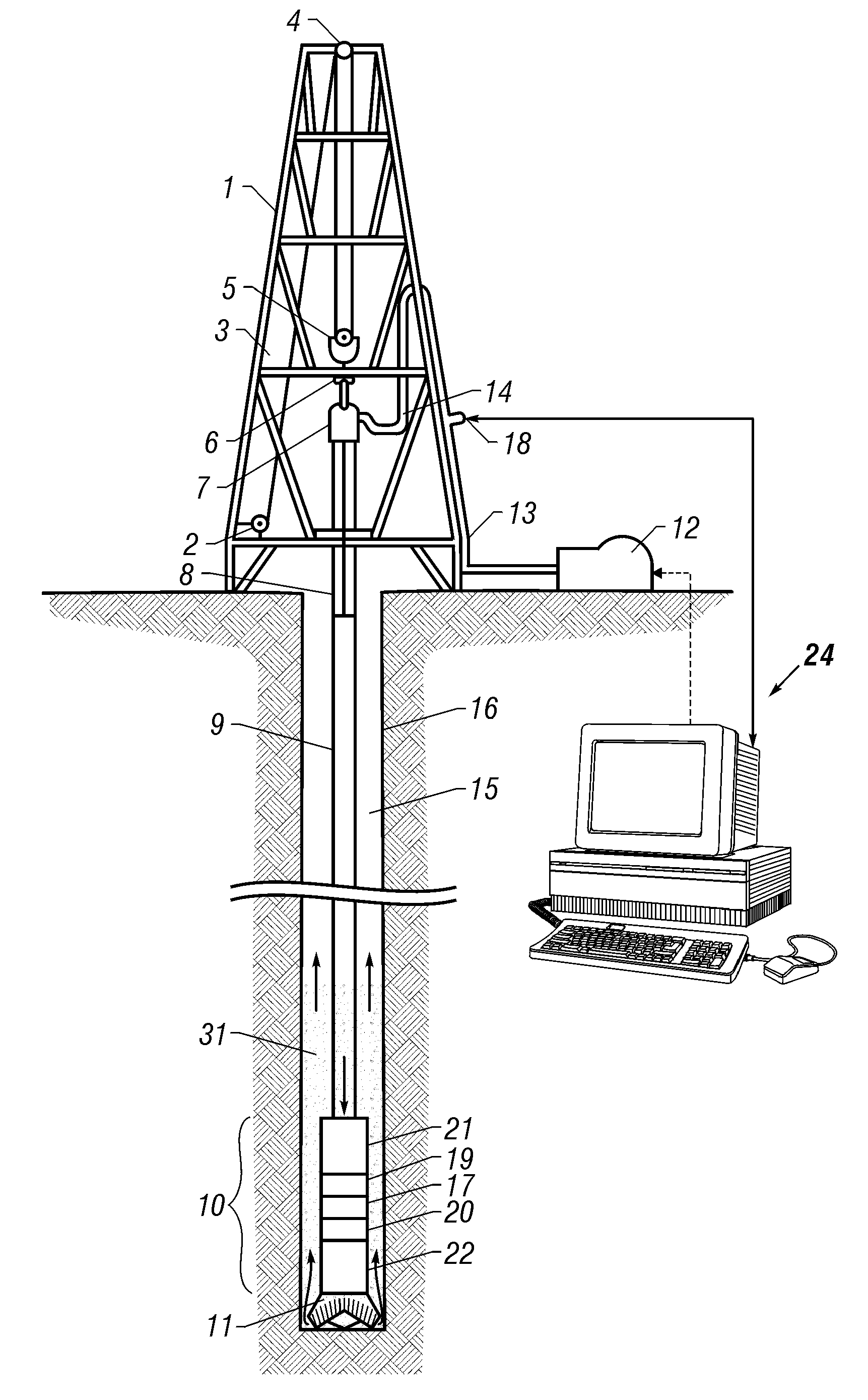
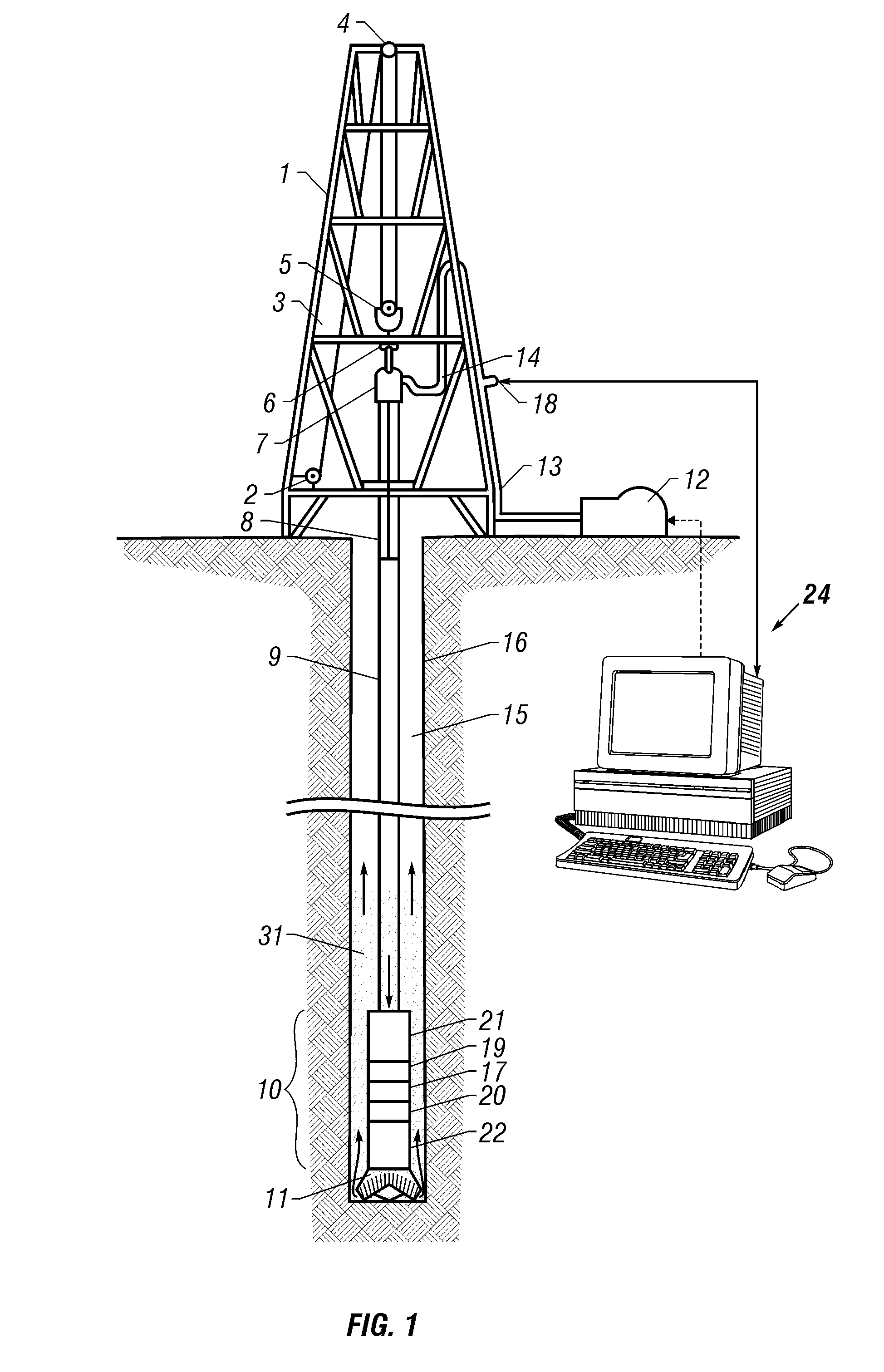
[0027]FIG. 1 is a schematic diagram showing a drilling rig 1 engaged in drilling operations. Drilling fluid 31, also called drilling mud, is circulated by pump 12 through the drill string 9 down through the bottom hole assembly (BHA) 10, through the drill bit 11 and back to the surface through the annulus 15 between the drill string 9 and the borehole wall 16. The BHA 10 may comprise any of a number of sensor modules 17, 20, 22 which may include, for example, formation evaluation (FE) sensors, sensors that provide information about operating conditions of the BHA, and survey sensors that provide survey information about the borehole. A partial list of FE sensors may include nuclear sensors, resistivity sensors, acoustic sensors, NMR sensors, etc. A partial list of the operating conditions may include temperature, pressure, rate of penetration, weight on bit, rotational speed, torque, and whirl measurements. Survey sensors may include a magnetometer, an accelerometer, and / or a gyrosc...


PUM


Abstract

A system for transmitting information in a well comprises a tubular string disposed in the well and having a drilling fluid flowing therethrough. A pulser is disposed in the tubular string and transmits a pulse synchronization marker comprising a chirp signal. A surface controller, acting under programmed instructions, detects the chirp signal adjusts a signal decoding technique based on the detected chirp signal.

Description

CROSS-REFERENCES TO RELATED APPLICATIONS[0001]This application claims priority from U.S. provisional patent application Ser. No. 60 / 773024 filed on Feb. 14, 2006.BACKGROUND OF THE INVENTION[0002]1. Field of the Invention[0003]The present invention relates to drilling fluid telemetry systems, and, more particularly, to a system and method for enhancing data transfer.[0004]2. Description of the Related Art[0005]Drilling fluid telemetry systems, generally referred to as mud pulse telemetry systems, are particularly adapted for telemetry of information between the bottom of a borehole and the surface of the earth during oil well drilling operations. The information telemetered often includes, but is not limited to, operational parameters, such as pressure, temperature, direction and deviation of the wellbore. Other parameters include well logging data such as electrical conductivity of the various formation layers, acoustic and nuclear properties, porosity, and pressure gradients relate...

Claims


Application Information

Patent Timeline
Patent Type & Authority Applications(United States)
IPC IPC(8): H04H9/00H04H60/31
CPCE21B47/18
Inventor KLOTZ, CHRISTIANRECKMANN, HANNOWASSERMANN, INGOLFMACPHERSON, JOHN D.ORTIZ, JOSE ALONSOBROOKS, ANDREW G.
Owner BAKER HUGHES INC
Why Eureka
Try Eureka