Controlling engine operation during diesel particulate filter regeneration to avoid runaway

a technology of diesel particulate filter and engine operation, which is applied in the direction of machines/engines, mechanical equipment, exhaust treatment electric control, etc., can solve the problems of increased stress in internal materials, more cracking of materials, and shock that cracks a substra

Inactive Publication Date: 2007-08-23
INT ENGINE INTPROP CO LLC
View PDF6 Cites 29 Cited by
  • Summary
  • Abstract
  • Description
  • Claims
  • Application Information

AI Technical Summary

Benefits of technology

[0022] In response to release of the accelerator the control system causes the engine to idle at a lower low idle speed that has been predetermined appropriate for low idling when the diesel particulate filter is not being regenerated but inappropriate when the diesel particulate filter is being regenerated because of the potential for causing on-going regeneration to become uncontrolled, and when the diesel particulate filter is being regenerated, to idle at a higher low idle speed sufficiently higher than the lower low idle speed to essentially eliminate the potential for continued diesel particulate filter regeneration becoming uncontrolled as the engine idles

Problems solved by technology

Such a high temperature shock increases stresses in the internal materials.
Even a single drop-to-idle event can create a shock that cracks a substrate.
Repeated shocks have a cumulative effect that can eventually lead to even more cracking of the material and resulting DPF failure, because a DPF will progressively lose soot trapping effectiveness as cracks propagate.
DPF failure within an applicable warranty period imposes a warranty cost on the manufacturer.

Method used


Image

  • Controlling engine operation during diesel particulate filter regeneration to avoid runaway
  • Controlling engine operation during diesel particulate filter regeneration to avoid runaway
  • Controlling engine operation during diesel particulate filter regeneration to avoid runaway

Examples


Embodiment Construction

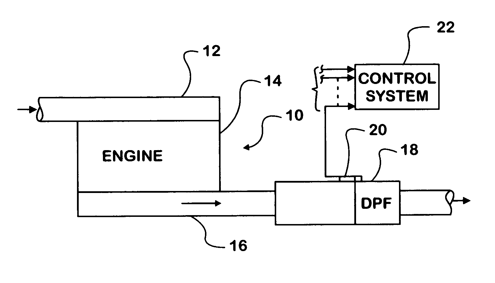
[0028]FIG. 1 shows a diesel engine 10 having an intake system 12 leading to an engine block 14 containing cylinders into which diesel fuel is injected by a fueling system and from which an exhaust system 16 conveys exhaust gases. Exhaust system 16 contains one or more exhaust after-treatment devices one of which is a diesel particulate filter (DPF) 18 having a catalyzed ceramic substrate for trapping diesel particulates.

[0029] When engine 10 is operating to propel a motor vehicle, such as a large truck, exhaust gas exits the engine combustion chambers to enter exhaust system 16 and pass through DPF 18 before eventually passing into the surrounding atmosphere.

[0030] Various sensors are associated with the after-treatment devices. One of them that is relevant to the specific embodiments discussed here is a DPF inlet temperature sensor 20 disposed to measure temperature at the inlet of DPF 18.

[0031] The inventive method is implemented in an engine control system 22 that processes va...


PUM


Abstract

A motor vehicle diesel engine (10) has an exhaust system (16) having a diesel particulate filter (18) that traps particulate matter in engine exhaust gases passing through the exhaust system. A control system (22) processes certain data to control engine and diesel particulate filter operation. In response to driver release of the accelerator, the engine decelerates toward idling at a lower low idle speed that has been predetermined appropriate for low idling when the diesel particulate filter is not being regenerated but inappropriate when the diesel particulate filter is being regenerated because of the potential for causing on-going regeneration to become uncontrolled. When the diesel particulate filter is being regenerated, a higher low idle speed sufficiently higher than the lower low idle speed is substituted as the low idle speed set-point essentially eliminating the potential for continuation of on-going diesel particulate filter regeneration becoming uncontrolled as the engine idles.

Description

FIELD OF THE INVENTION [0001] This invention relates generally to emission control systems of internal combustion engines, more particularly diesel engines that have certain exhaust gas treatment devices for treating exhaust gases passing through their exhaust systems. The invention more especially also relates to a system and method for controlling engine operation in ways that avoid on-going controlled regeneration of a diesel particulate filter (DPF) from becoming uncontrolled when the engine is decelerated to low idle speed. BACKGROUND OF THE INVENTION [0002] A known system for treating exhaust gas passing through an exhaust system of a diesel engine comprises a diesel oxidation catalyst (DOC) associated with a diesel particulate filter (DPF). The combination of these two exhaust gas treatment devices promotes chemical reactions in exhaust gas and traps diesel particulate matter (DPM) as exhaust flows through the exhaust system from the engine, thereby preventing significant amo...

Claims


Application Information

Patent Timeline
Patent Type & Authority Applications(United States)
IPC IPC(8): F01N3/00F01N3/10
CPCY02T10/47F01N9/002Y02T10/40
Inventor BERKE, PAUL L.
Owner INT ENGINE INTPROP CO LLC
Why Eureka
Try Eureka