In situ method and system for extraction of oil from shale

a technology of oil extraction method and oil extraction system, which is applied in the direction of fluid removal, insulation, borehole/well accessories, etc., can solve the problems of substantial closure, risk of polluting the environment, and risk of losing expensive heating fluid, and achieve the effect of promoting the flow of retort vapors

Active Publication Date: 2007-08-23
AMERICAN SHALE OIL
View PDF2 Cites 90 Cited by
  • Summary
  • Abstract
  • Description
  • Claims
  • Application Information

AI Technical Summary

Benefits of technology

[0014] This invention is directed to a system and process for retorting and gathering hydrocarbons from oil shale. Heat energy is delivered to a subterranean body of oil shale to be retorted by drilling cased wells down into the oil shale deposit, to a proximal end of the bottom of the body of oil shale to be retorted, and then under and across the body of oil shale to be retorted, to its distal end. The casing under the body of oil shale to be retorted is a fluid transmission pipe through which a heated fluid (steam or a synthetic fluid) circulates; the heating fluid is at a temperature sufficient to retort oil shale. The fluid transmission pipe is part of a substantially closed loop heat delivery module, so that the heating fluid does not physically contact the oil shale or other subterranean environment and thus risk polluting it or risk losing expensive heating fluid. (The system is termed substantially closed, because some leakage at joints or at pressure relief valves is unavoidable,

Problems solved by technology

The fluid transmission pipe is part of a substantially closed loop heat delivery module, so that the heating fluid does not physically contact the oil shale or other subterranean environment and thus risk pollu

Method used


Image

  • In situ method and system for extraction of oil from shale
  • In situ method and system for extraction of oil from shale
  • In situ method and system for extraction of oil from shale

Examples


first embodiment

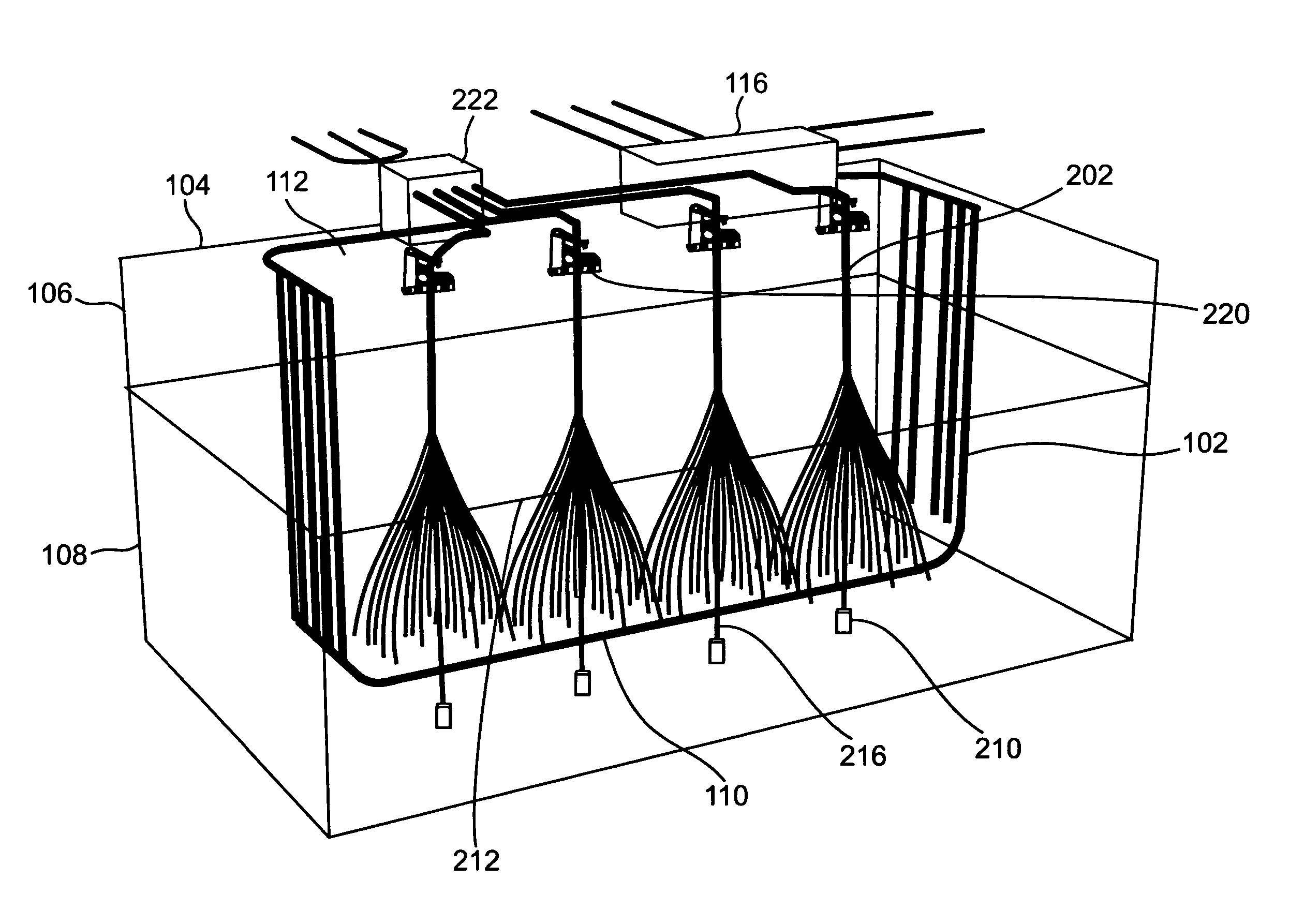
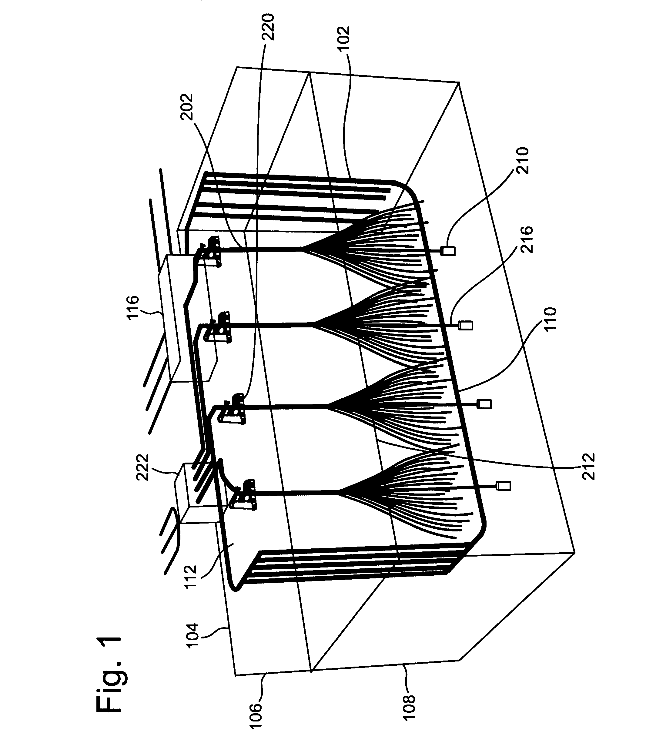
[0024] For this small scale embodiment, five wells are drilled for energy delivery and four wells are drilled for shale oil and gas recovery from a body of oil shale to be retorted, which is under a plot of land approximately 100 feet wide and 2000 feet long. (The longer dimension of the plot is up to approximately 1000 feet longer than the 1000-foot operational part of the wells, because an up to approximately 500-foot radius of curvature is required for the pipe to make a transition from a vertical to a horizontal orientation, and vice versa—as explained below.) The number of energy delivery wells drilled determines the production rate and the concomitant required heat input. The number and distribution of wells therefore reflects site-specific engineering trade-offs. The entry wells for energy delivery are at one 100-foot wide end of the plot and the exit wells are located at the other end; a single well drilling pad may be used for all five entry wells and another for all five e...

second embodiment

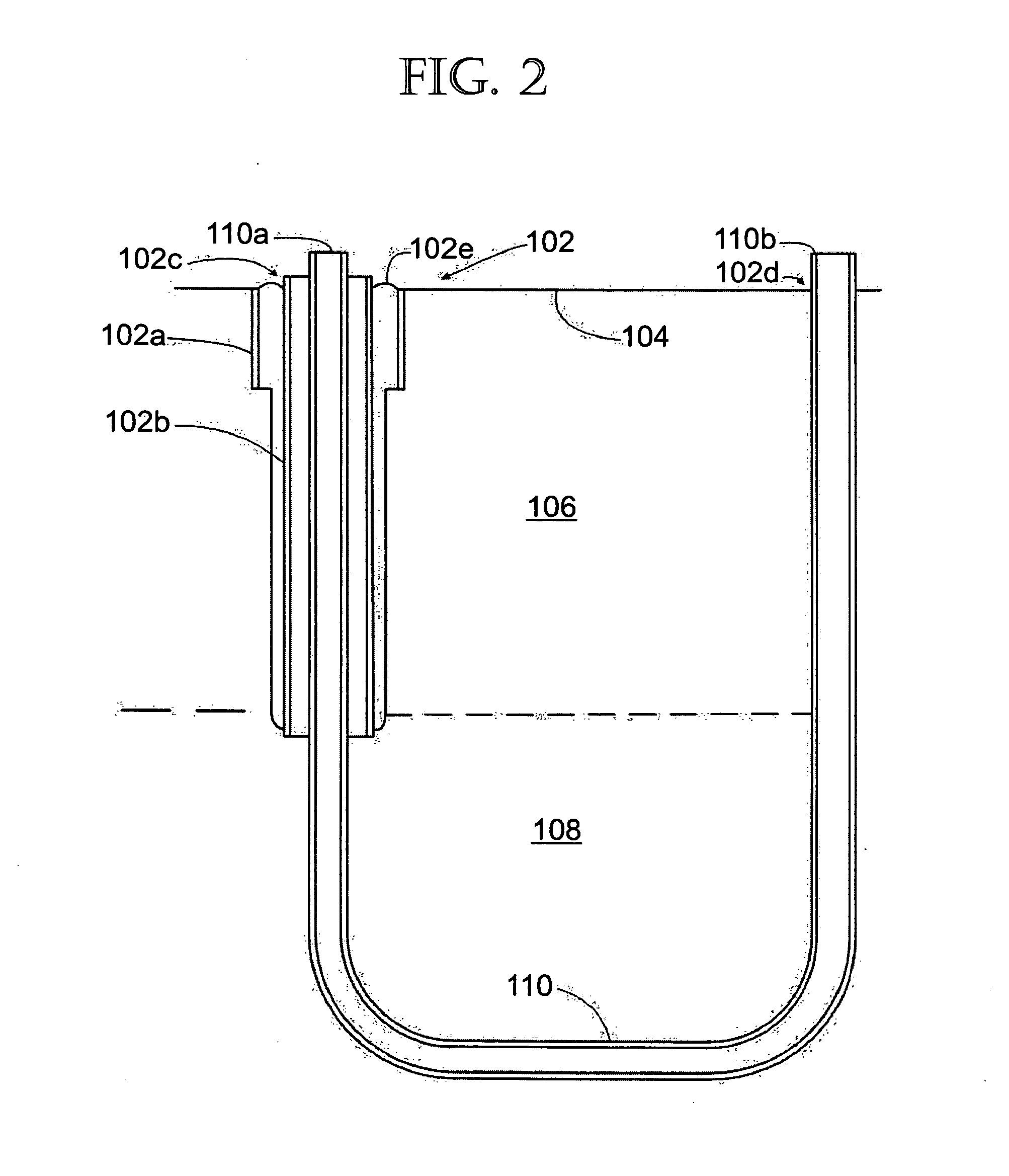
[0070] The second illustrative embodiment is a scaled up application of the principles described above in connection with the first embodiment. This embodiment describes the extraction of hydrocarbons from a plot of 20 acres, where each well pattern is directed to a 400×2000 foot subterranean body of oil shale to be retorted whose top is located 1000 feet below the surface and contains a 1000 foot thick body of oil shale to be retorted. In this embodiment, energy delivery subsystem 100 comprises a row of approximately 20 cased energy delivery wells 102 approximately 20 feet apart from one another. The cased energy delivery wells are divided between two drill pads at each of the entry and exit ends respectively. Each well 102 is drilled from the site surface 104 down through approximately 1000 feet of overburden 106 and then down through approximately 1000 feet of oil shale zone 108. Each well 102 then extends generally horizontally across the site for about 2000 feet, and then retur...


PUM


Abstract

A system and process is disclosed for retorting oil shale and extracting shale oil and other hydrocarbons therefrom, in which a cased heat delivery well is drilled generally vertically through an overburden and then through a body of oil shale to be retorted to the bottom thereof, generally horizontally under the body of oil shale to be retorted, and then back to the earth surface. Heat energy is transmitted conductively to the body of oil shale to be retorted from a closed loop heat delivery module in the well, the module comprising a fluid transmission pipe containing a heating fluid heated to at least a retorting temperature. Heat energy is also transmitted to the body of oil shale to be retorted above the fluid transmission pipe by vapor conduits that conduct retort vapors upward through the body of oil shale to be retorted; the ascending retort vapors condense and reflux, delivering their latent heat of vaporization to the body of oil shale to be retorted, and the condensed retort liquids descend. If not recycled, the retort liquids are collected in a sump at the bottom of a production well and are transmitted to the surface for processing. The vapor conduits communicate at upper ends thereof with the production well, so that vapors that do not reflux are collected in the production well and are transmitted to the surface for processing.

Description

PRIORITY CLAIM [0001] This application claims priority to Provisional Patent Application No. 60 / 760,698, entitled “EGL Oil Shale Process—An in-situ, thermal recovery process (ISTRP) utilizing a closed loop, largely self-sustaining, heating system and directionally drilled clusters of small, open wellbores designed to facilitate heat transfer and collection of thermally generated oil and natural gas,” mailed on Jan. 20, 2006, which application is incorporated herein by reference.BACKGROUND [0002] The present invention relates generally to processes and apparatus for in situ extraction or production of hydrocarbons—including oil and gas—from underground oil shale formations. In particular, the present invention concerns a method and system in which an energy source, preferably oil shale or hydrocarbons derived therefrom, is used to heat a closed system, thereby lessening adverse environmental impacts, the closed system providing the heat to retort the oil shale. Oil Shale [0003] Oil s...

Claims


Application Information

Patent Timeline
IPC IPC(8): E21B43/24
CPCE21B43/30E21B43/24
Inventor HARRIS, HARRY GORDONLERWICK, PAULVAWTER, R. GLENN
Owner AMERICAN SHALE OIL
Why Eureka
Try Eureka