Endoscope observation device, observation device and observation method using endoscope

a technology of observation device and endoscope, which is applied in the field of endoscope observation device, observation device and observation method using endoscope, can solve the problem of not being able to measure the distance of the space filled with air, and achieve the effect of accurate measurement of distan

Active Publication Date: 2007-08-23
OLYMPUS CORP
View PDF9 Cites 74 Cited by
  • Summary
  • Abstract
  • Description
  • Claims
  • Application Information

AI Technical Summary

Benefits of technology

[0012]It is an object of the invention to provide an endoscope observation device, the observation device, and the observation method using the endoscope which allow accurate measurement of the distance between

Problems solved by technology

It is not capable of measuring the d

Method used


Image

  • Endoscope observation device, observation device and observation method using endoscope
  • Endoscope observation device, observation device and observation method using endoscope
  • Endoscope observation device, observation device and observation method using endoscope

Examples


first embodiment

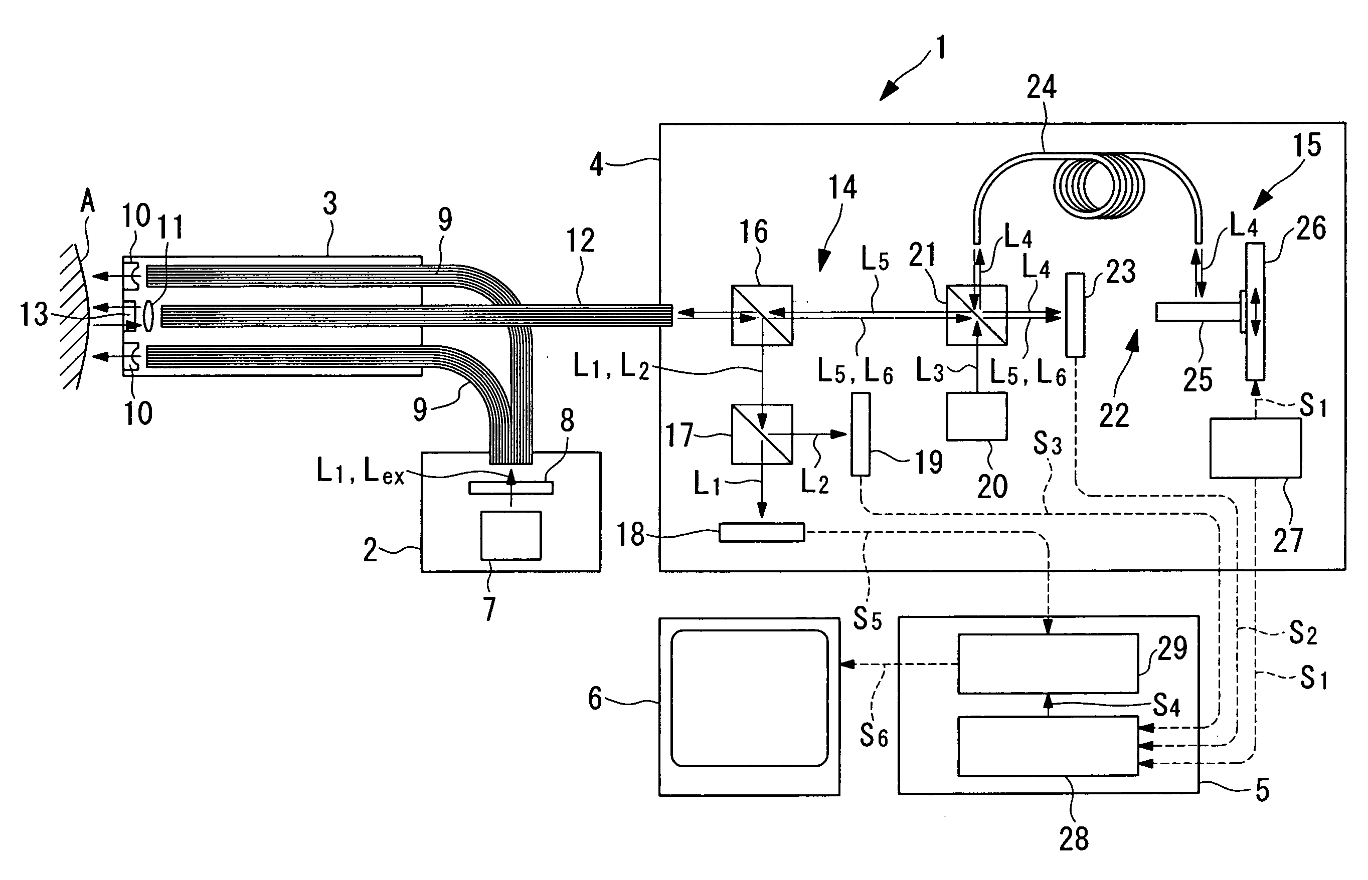
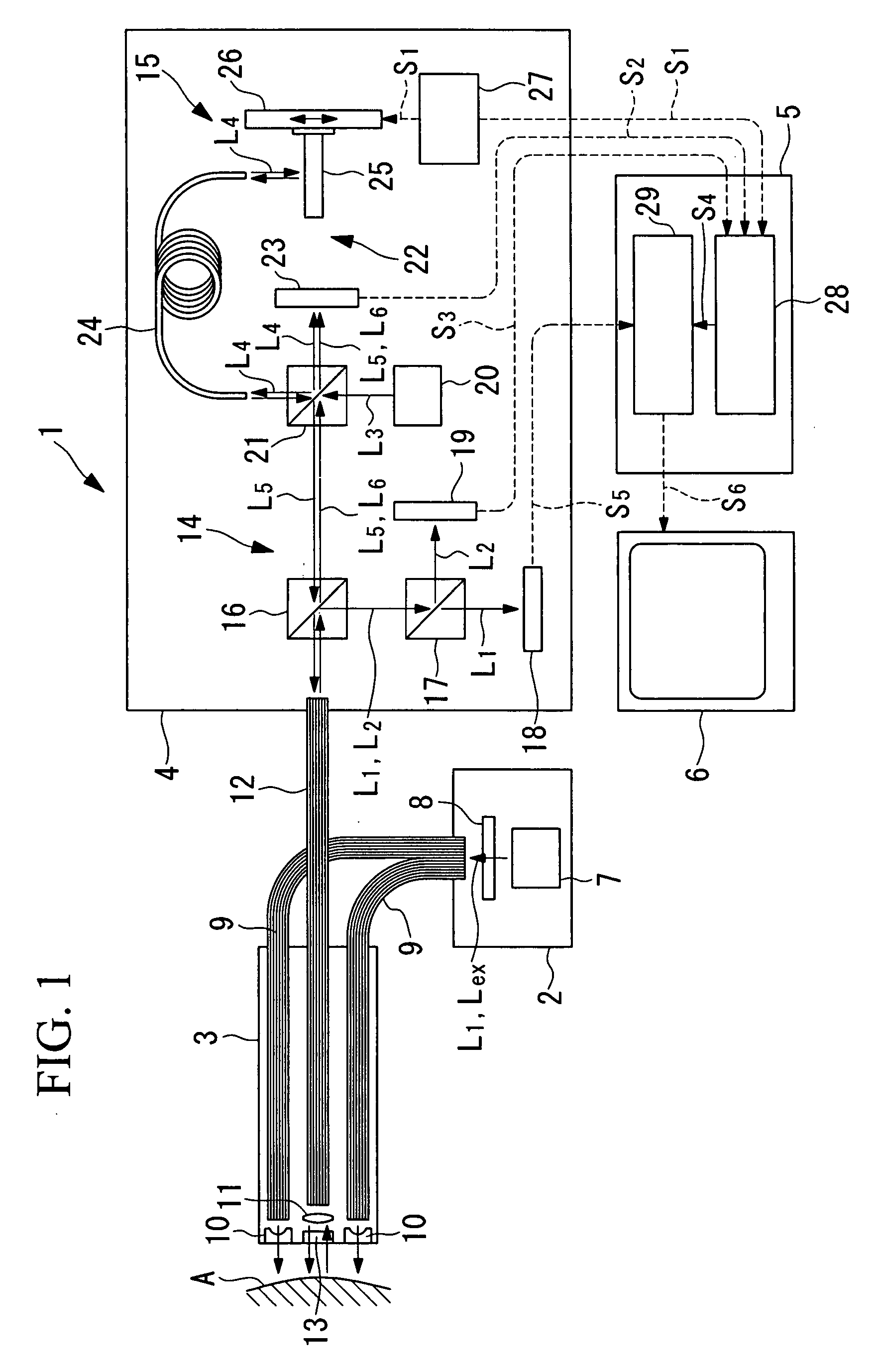
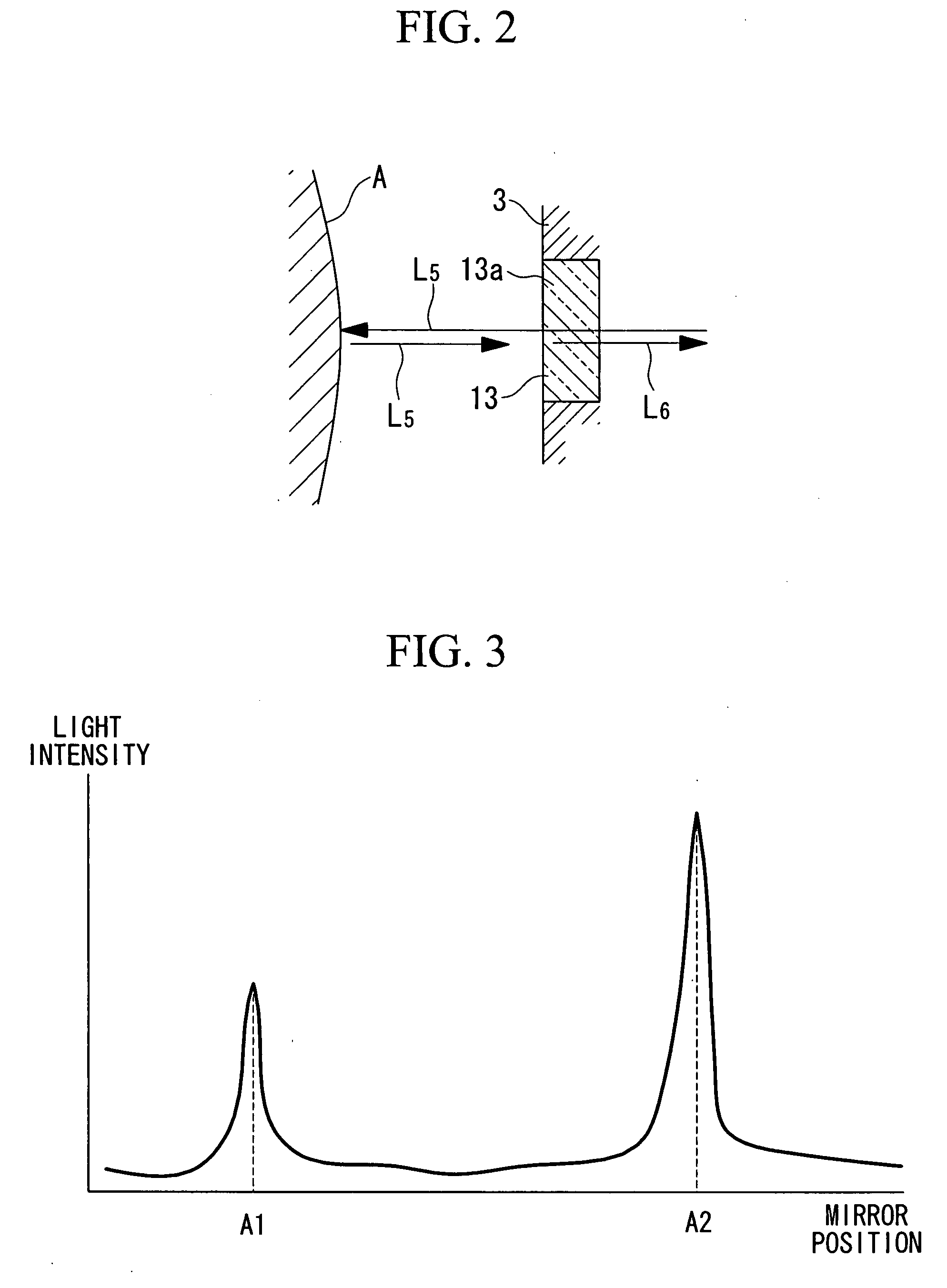
[0085]An endoscope observation device according to the invention will be described referring to FIGS. 1 to 3.

[0086]An endoscope observation device 1 of the embodiment includes a light source unit 2, a long and thin insertion portion 3 connected to the light source unit 2 and inserted into the body cavity, a detection unit 4 connected to the insertion portion 3 to detect the return light from a body tissue A as a specimen, an image processing unit 5 that forms the image of the body tissue A based on a detection signal of the detection unit 4, and an image display unit 6 that displays the image of the body tissue A produced in the image processing unit 5.

[0087]Referring to FIG. 1, the light source unit 2 includes a light source 7 that emits the broadband light, for example, a xenon lamp, a halogen lamp and the like, and a filter 8 that allows transmission of white light L1 and excitation light Lex emitted from the light source 7.

[0088]The insertion portion 3 includes a light guide (or...

second embodiment

[0122]An endoscope observation device 40 according to the invention will be described referring to FIG. 10.

[0123]The same components as those of the endoscope observation device 1 according to the first embodiment as described above will be designated with the same reference numerals and explanations thereof, thus, will be omitted.

[0124]The endoscope observation device 40 of the embodiment is different from the endoscope observation device 1 according to the first embodiment in the structure of the reference light optical path length adjustment unit 41.

[0125]In the embodiment, the reference light optical path length adjustment unit (optical path length adjustment unit) 41 includes a plurality of beam splitters (reference light split unit) 42, 43 and a mirror 44 for splitting the reference light L4 propagated by the fiber bundle 24 into a plurality of lights, a plurality of scanning mirrors 25 which reflect the respective split reference lights L4, a plurality of mirror movement mech...

third embodiment

[0129]An endoscope observation device 60 according to the invention will be described referring to FIG. 11.

[0130]The same components as those of the endoscope observation unit 40 according to the second embodiment will be designated with the same reference numerals, and explanations thereof, thus, will be omitted.

[0131]The endoscope observation device 60 of the embodiment is different from the endoscope observation device 40 according to the second embodiment in the structure of the reference light optical path length adjustment unit 61 as shown in FIG. 11.

[0132]In the embodiment, the reference light optical path length adjustment unit (optical path length adjustment unit) 61 includes a plurality of beam splitters 62, 63 and a mirror 64 for splitting the reference light L4 propagated by the fiber bundle 24 into a plurality of lights, optical modulators 65 to 67 for modulating the plurality of split reference lights L4 at the different frequencies, a plurality of scanning mirrors 25 ...


PUM


Abstract

A high accurate image of a specimen is obtained by accurately measuring a distance between the specimen and a tip of a light emitting portion that irradiates a light to the specimen. An endoscope observation device includes the light emitting portion that irradiates the light to the specimen and a light receiving portion that receives an observation light returning from the specimen so as to form an image of the observation light received by the light receiving portion. The endoscope observation device is equipped with a distance measurement unit that measures an absolute distance between the tip of the insertion portion and the specimen through an interference of the low coherence light, a correction unit that corrects the brightness information of the observation light based on the absolute distance measured by the distance measurement unit, and an image forming unit that forms the image of the specimen based on the brightness information of the observation light corrected by the correction unit.

Description

BACKGROUND OF THE INVENTION[0001]1. Field of the Invention[0002]The invention relates to an endoscope observation device, an observation device and an observation method using the endoscope.[0003]This application is based on Japanese Patent Application No. 2006-046639, the content of which is incorporated herein by reference.[0004]2. Description of Related Art[0005]Generally, a fluorescent endoscope system for observing the fluorescence generated by irradiating the excitation light to a live body tissue has been disclosed by Japanese Unexamined Patent Application, Publication No. 10-243920 (hereinafter referred to as Patent Document 1), for example.[0006]The aforementioned fluorescent endoscope system is structured to irradiate the excitation light to a live body, and to detect the fluorescence naturally emitted from the live body or the fluorescence from the medicine which has been infused to the live body in the form of two-dimensional images. The fluorescent endoscope system allo...

Claims


Application Information

Patent Timeline
IPC IPC(8): A61B1/06A61B1/00
CPCA61B1/043A61B1/045A61B1/0638A61B5/0071A61B1/07A61B5/1076A61B1/00165A61B1/00183A61B5/0084A61B5/0062A61B5/0066A61B1/0627
Inventor ISHIHARA, YASUSHIGE
Owner OLYMPUS CORP
Why Eureka
Try Eureka