Method of manufacturing an acoustic mirror for piezoelectric resonator and method of manufacturing a piezoelectric resonator

a piezoelectric resonator and acoustic mirror technology, applied in the field of piezoelectric resonators, can solve the problems of reduced piezoelectric coupling of the active layer, reduced piezoelectric coupling quality, and inability to completely planarize the topology resulting in this way, and achieve excellent uniformity

Inactive Publication Date: 2007-08-30
CONTRIA SAN LIABILITY
View PDF10 Cites 16 Cited by
  • Summary
  • Abstract
  • Description
  • Claims
  • Application Information

AI Technical Summary

Benefits of technology

[0012] Starting from this prior art, it is an object of the present invention to provide an improved method of manufacturing an acoustic mirror for a piezoelectric resonator, which enables mirrors with excellent uniformity in the layer deposition, as well as a planar surface of the entire mirror structure.

Problems solved by technology

The disadvantage of this procedure is that the topology resulting hereby can no longer be completely planarized.
Due to the unevenness, undesired modes are induced in the resonator and / or a reduction in the quality of the resonator is caused.
This problem is very critical in so far as already small steps or remaining topologies of several percent of the layer thickness have significant influence on the operation behavior of such a resonator.
This procedure is disadvantageous regarding the resulting strong topology in the layers lying above the mirror 106, in particular, with reduced piezoelectric coupling of the active layer 112 as well as increased excitation of undesired vibrational modes arising.
The method described on the basis of FIG. 2 is disadvantageous in that the layers are slightly thinner in the corners of the mirror pit 126, and a slight key topology in the resonator region 122, indicated with the reference numeral 130, develops, which again leads to increased excitation of undesired modes and to reduced resonator quality.

Method used


Image

  • Method of manufacturing an acoustic mirror for piezoelectric resonator and method of manufacturing a piezoelectric resonator
  • Method of manufacturing an acoustic mirror for piezoelectric resonator and method of manufacturing a piezoelectric resonator
  • Method of manufacturing an acoustic mirror for piezoelectric resonator and method of manufacturing a piezoelectric resonator

Examples


Embodiment Construction

[0036] In the subsequent description of the preferred embodiments of the present invention, the same or similarly acting elements are provided with the same reference numerals.

[0037] In the subsequent explanations, it is assumed that the layer to be structured has the higher acoustic impedance. The present invention is not limited to this embodiment, the inventive method rather works in fully analog manner when the conductive layer has the smaller acoustic impedance.

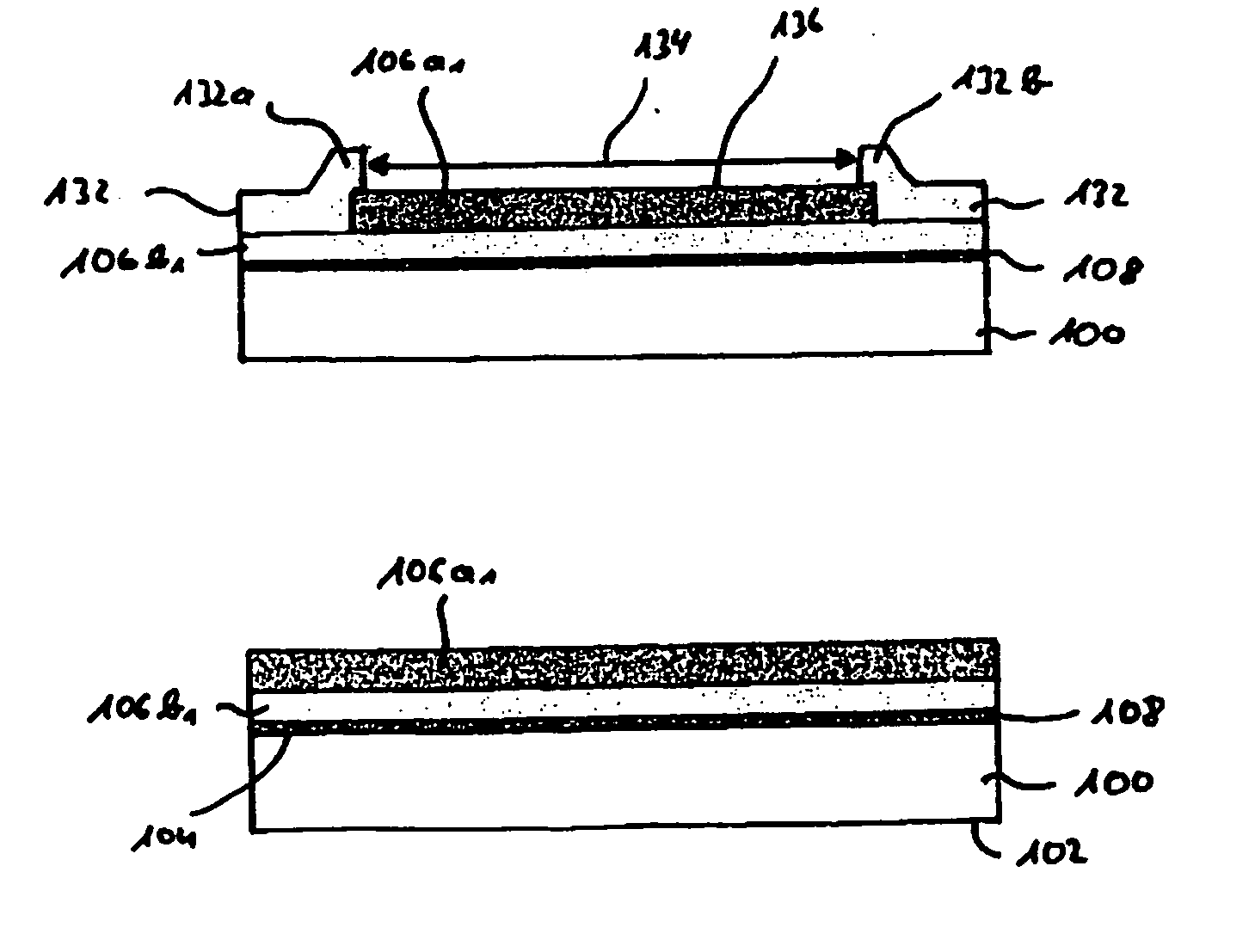
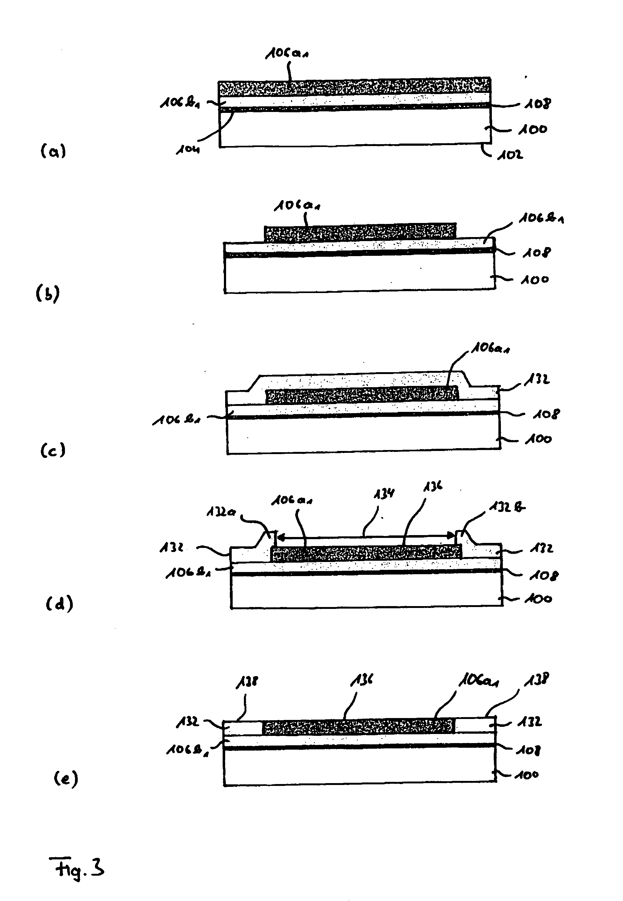
[0038] On the basis of FIG. 3, the concept underlying the present invention will be explained in greater detail. In FIG. 3(a), a substrate 100 is shown, on the upper surface 104 of which a first layer 106b1 with low acoustic impedance, e.g. an oxide, is arranged, on which in turn a first layer 106a1 with high acoustic impedance, e.g. a tungsten layer or another suitable conductive layer, has been deposited on the whole area. In addition, as it has been described above, one or more intermediate layers may be provided be...


PUM

PropertyMeasurementUnit
acoustic impedanceaaaaaaaaaa
conductiveaaaaaaaaaa
dimensionsaaaaaaaaaa

Abstract

A mirror for a piezoelectric resonator consisting of alternately arranged layers of high and low acoustic impedance is manufactured by at first producing a first layer on which a second layer is produced, so that the second layer partially covers the first layer. Then, a planarization layer is applied on the first layer and on the second layer. Subsequently, a portion of the second layer is exposed by structuring the planarization layer, wherein the portion is associated with an active region of the piezoelectric resonator. Finally, the resulting structure is planarized by removing the portions of the planarization layer remaining outside the portion.

Description

BACKGROUND OF THE INVENTION [0001] 1. Field of the Invention [0002] The present invention relates to the field of piezoelectric resonators, e.g. BAW (bulk acoustic wave) resonators, and particularly to a method of manufacturing an acoustic mirror for a piezoelectric resonator, as well as to a method of manufacturing a piezoelectric resonator. In particular, the present invention relates to a method of manufacturing an acoustic mirror, which is highly planar and has both excellent uniformity in the layer deposition and a planar surface of the entire mirror structure. [0003] 2. Description of the Related Art [0004] Radio-frequency filters based on BAW resonators are of great interest for many RF applications. Substantially, there are two concepts for BAW resonators, so-called thin film BAW resonators (FBAR), on the one hand, as well as so-called solidly mounted resonators (SMR). Thin film BAW resonators include a membrane on which the layer sequence consisting of the lower electrode, ...

Claims


Application Information

Patent Timeline
Patent Type & Authority Applications(United States)
IPC IPC(8): H04R17/00
CPCH03H3/02H03H9/02086H03H9/175H03H2003/025Y10T29/49004Y10T29/435Y10T29/4913Y10T29/49005Y10T29/42Y10T29/43
Inventor THALHAMMER, ROBERTMARKSTEINER, STEPHANFATTINGER, GERNOT
Owner CONTRIA SAN LIABILITY
Why Eureka
Try Eureka