Vertical Heat Treatment System And Method Of Transferring Process Objects

a heat treatment system and process object technology, applied in the direction of furnaces, charge manipulation, muffle furnaces, etc., can solve the problems of affecting the efficiency of the process, so as to avoid problems such as damage to the process object w, the durability of the fixed engagement member and the movable engagement member can be improved, and the effect of improving the durability

Inactive Publication Date: 2007-08-30
TOKYO ELECTRON LTD
View PDF15 Cites 11 Cited by
  • Summary
  • Abstract
  • Description
  • Claims
  • Application Information

AI Technical Summary

Benefits of technology

[0012] Preferably, each of the substrate support devices is provided with seats that receive front and rear peripheral portions, respectively, such that a gap is formed between a lower surface of the substrate supporting device and an upper surface of the process object. Thus, the upper surface of each process object can be prevented from being rubbed and damaged by the lower surface of the substrate support device, when the process object is gripped.
[0013] Preferably, each of the ring-shaped support plates has cutouts for preventing the ring-shaped support plate from colliding with the fixed engagement member and the movable engagement member. Thus, the gripping mechanism can securely grip the process object without colliding with by the ring-shaped support plate.
[0014] Preferably, at least one of the substrate support device is provided with a mapping sensor, which is configured to detect a position of a detection object by moving the substrate support device such that a light beam traveling between two distal ends of the substrate support device is interrupted by the detection object. Thus, the existence of a process object W on each of the ring-shaped support plate can be detected by scanning plural process objects W placed on the respective ring-shaped support plates 15 in the holder 9 along the direction in which the process objects W are arranged, and thereby the mapping of the process objects can be performed. Further, since it is possible to detect whether a process object W sticks out of the holder 9 before and after the heat treatment of the process object W, troubles such as damage of the process object W can be avoided.
[0015] Preferably, the fixed engagement member and the movable engagement member are formed of a heat-resistant resin. Thus, durability of the fixed engagement member and the movable engagement member can be improved. Further, these engagement members do not act as contaminant sources for the process object.

Problems solved by technology

Thus, a long time is needed for wafer transfer operation, which inhibits improvement of throughput.
Thus, the maximum number of wafers to be held (treated) in a holder of a predetermined size is about 50 at most, which also inhibits improvement of throughput.
Meanwhile, in the transfer mechanism B, all the engagement members disposed on the distal end side and the proximal end side of the fork are movable, and thus a complicated structure is added to the fork.
Therefore, the height of the fork is undesirably increased, which makes it difficult to reduce the arrangement pitch of the ring-shaped support plates in the holder.

Method used


Image

  • Vertical Heat Treatment System And Method Of Transferring Process Objects
  • Vertical Heat Treatment System And Method Of Transferring Process Objects
  • Vertical Heat Treatment System And Method Of Transferring Process Objects

Examples


Embodiment Construction

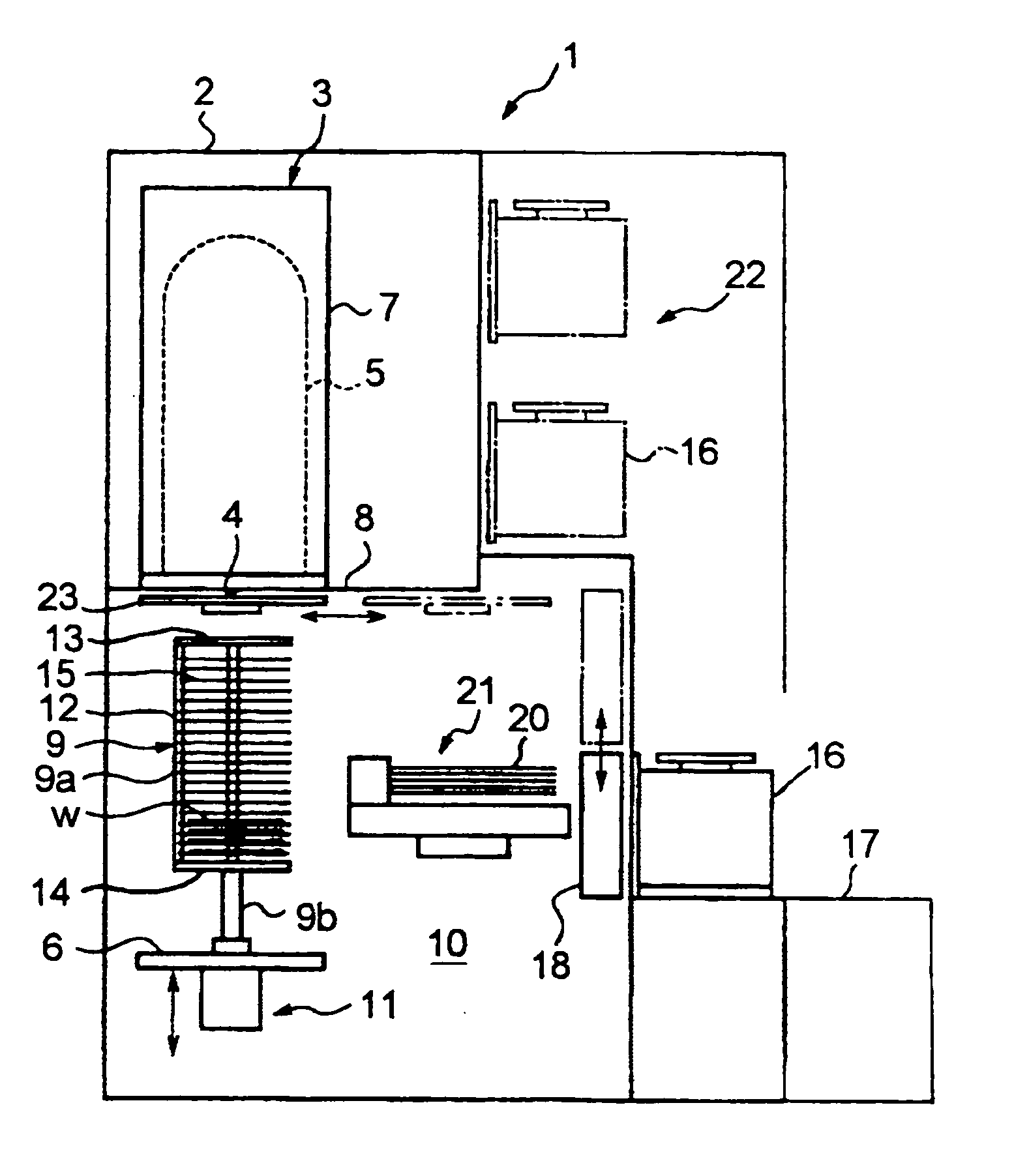
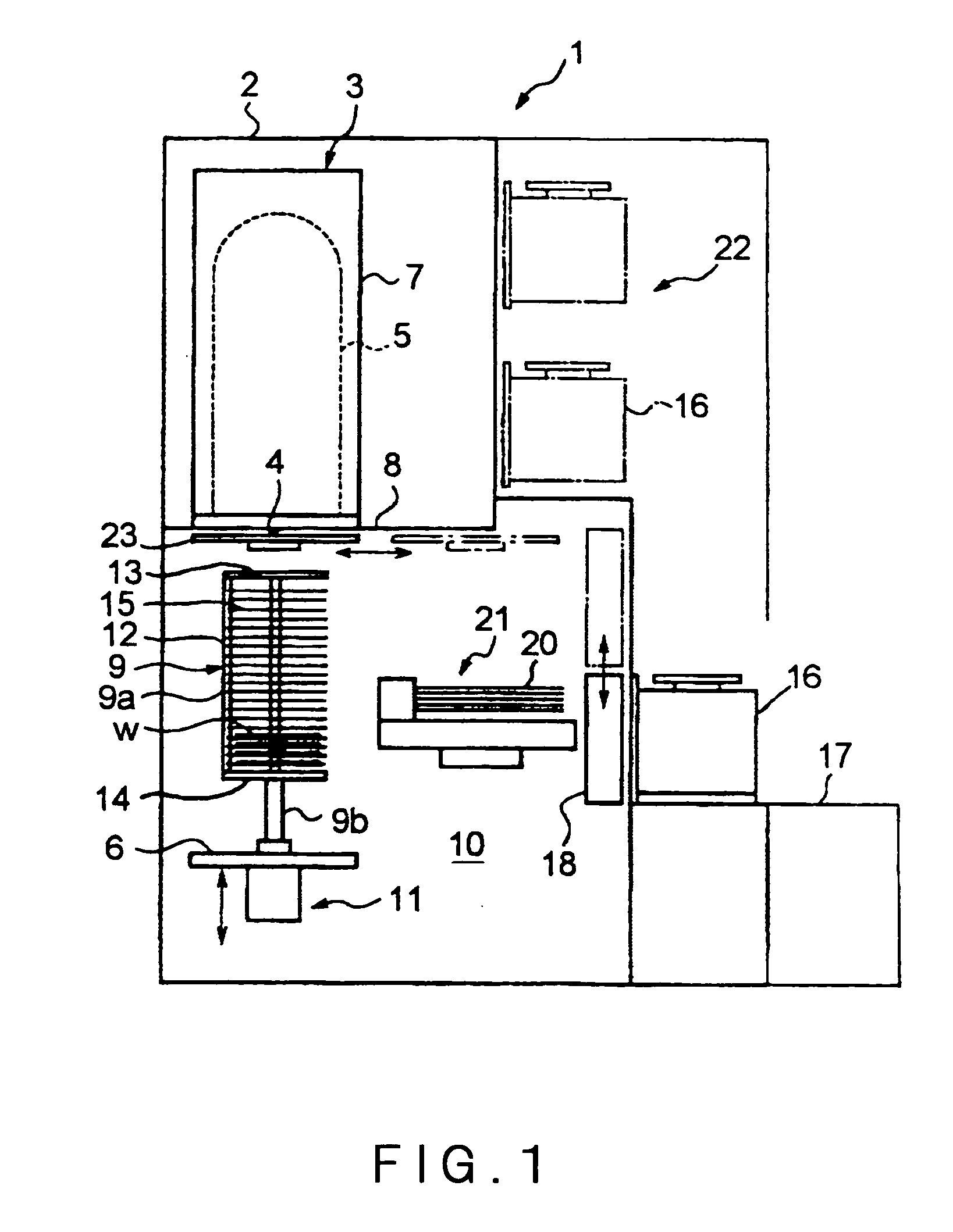
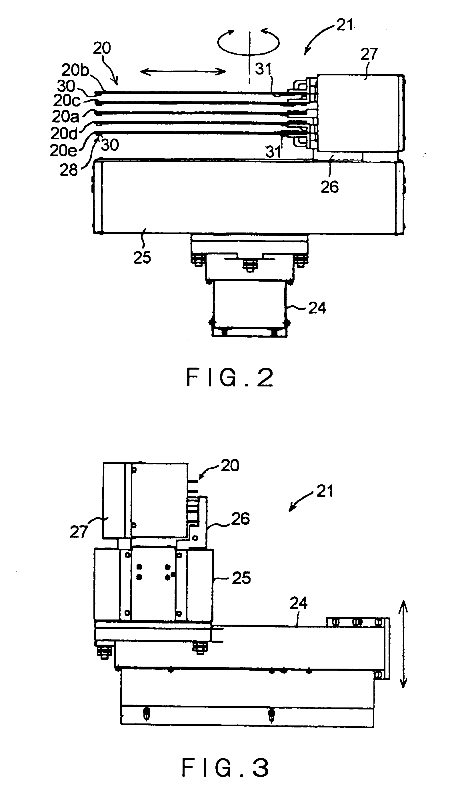
[0046] The best mode for carrying out the invention will be described in detail with reference to the accompanying drawings. FIG. 1 is a longitudinal cross-sectional view schematically showing a vertical heat treatment system in one embodiment of the present invention. FIG. 2 is a side view of a transfer mechanism. FIG. 3 is a side view of the transfer mechanism of FIG. 2 viewed from another side. FIG. 4 is a plan view of a substrate support device and related parts of the transfer mechanism. FIG. 5 is a plan view of a ring-shaped support plate.

[0047] As shown in FIG. 1, a vertical heat treatment system 1 includes an enclosure 2 serving as a frame of the system. A vertical heat treatment furnace 3 is provided in the enclosure 2 at an upper part thereof. The heat treatment furnace 3 accommodates process objects (also referred to as “substrates to be processed”) such as semiconductor wafers W of a thin circular disk shape, and performs a predetermined treatment, e.g., a CVD treatment...


PUM


Abstract

Disclosed is an improved transfer mechanism 21 that transfers, in a vertical heat treatment system, process objects W between a container (carrier) 16 for containing therein plural process objects, and a holder (boat) 9 for holding plural process objects at vertical intervals via ring-shaped support plates 15. The transfer mechanism 21 includes plural substrate support devices 21 spaced at intervals, and each of the substrate support devices 21 has a gripping mechanism 28 for gripping a process object W on the under side of the respective one of the substrate support devices 20. The gripping mechanism 28 includes a fixed engagement member 30 fixedly provided on a distal end of the substrate support device 20 to be engaged with a front edge of a process object W, and a movable engagement member 31 movably attached to a proximal end of the substrate support device 20 to be engaged with a rear edge of the process object W. Plural process objects W can be rapidly, securely transferred at the same time. A simple structure of the gripping mechanism 28 reduces the thickness of the substrate support device 21, so that the intervals of the ring-shaped support plates 15 can be reduced. Thus, the number of process objects to be simultaneously treated in a heat treatment furnace can be increased. As a result, improvement in throughput can be achieved.

Description

TECHNICAL FIELD [0001] The present invention relates to a vertical heat treatment system and a method of transferring process objects, and more particularly to improvement in a transfer system enabling it to transfer plural process objects collectively to a holder having ring-shaped support plates. BACKGROUND ART [0002] A manufacturing process of a semiconductor device includes various process steps that perform various heat treatments, such as an oxidation treatment, a diffusion treatment, a CVD treatment, and an annealing treatment, to a process object, e.g., a semiconductor wafer. A vertical heat treatment system capable of heat-treating plural wafers at one time has been used as one of heat treatment systems for performing the foregoing process steps. [0003] The vertical heat treatment system includes: a heat treatment furnace having a furnace throat in its lower end; a lid that hermetically closes the furnace throat; a holder (also referred to as “wafer boat”) disposed on the l...

Claims


Application Information

Patent Timeline
Patent Type & Authority Applications(United States)
IPC IPC(8): B65D85/00F27B5/04F27B5/12B65G49/07F27B5/13F27B17/00F27D3/12H01L21/22H01L21/31H01L21/324H01L21/67H01L21/677H01L21/68H01L21/683H01L21/687
CPCF27B5/04F27B5/12F27B5/13H01L21/68707H01L21/67757H01L21/67781F27B17/0025B65G49/07F27D3/12
Inventor ASARI, SATOSHIMIHARA, KATSUHIKOKIKUCHI, HIROSHI
Owner TOKYO ELECTRON LTD
Why Eureka
Try Eureka