Transmitter

a transmitter and receiver technology, applied in the field of transmitters, can solve the problems of pcde, evm degraded, pcde (error vector magnitude), peak electric power restored, etc., and achieve the effect of reducing the peak level

Inactive Publication Date: 2007-08-30
KOKUSA ELECTRIC CO LTD
View PDF10 Cites 31 Cited by
  • Summary
  • Abstract
  • Description
  • Claims
  • Application Information

AI Technical Summary

Benefits of technology

[0024] Therefore, a window multiplication type intermediate frequency limiter means can be used to effectively reduce the peak level.
[0025] Moreover, for modes of the limiter, there are a level fluctuation mode, a phase fluctuation mode, a window multiplication mode and so on, various modes may be used. For example, it was confirmed by experiment that when a...

Problems solved by technology

However, a problem arises that peak electric power is restored when band limitation (waveform shaping) is performed by the band limiting filters F1 to Fn and the like positioned in the subsequent stage thereof.
In addition, in the technique described in Patent Reference 2, when a plurality of peaks exists at positions close to each other (closer time instants) in transmitting signals, a peak suppression coefficient generated due to one of the peaks is overlapped with a peak suppression coefficient generated due to the other of the peaks to excessively reduce the level of the transmitting signal, causing a problem that a...

Method used


Image

  • Transmitter
  • Transmitter
  • Transmitter

Examples


embodiment 1

[0048] A first embodiment of the invention will be described.

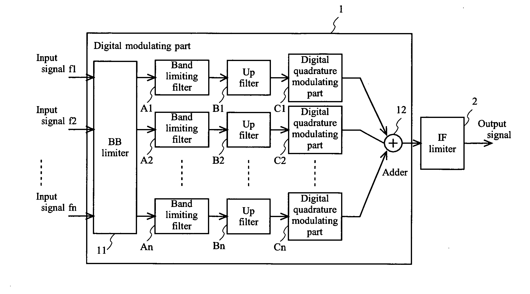
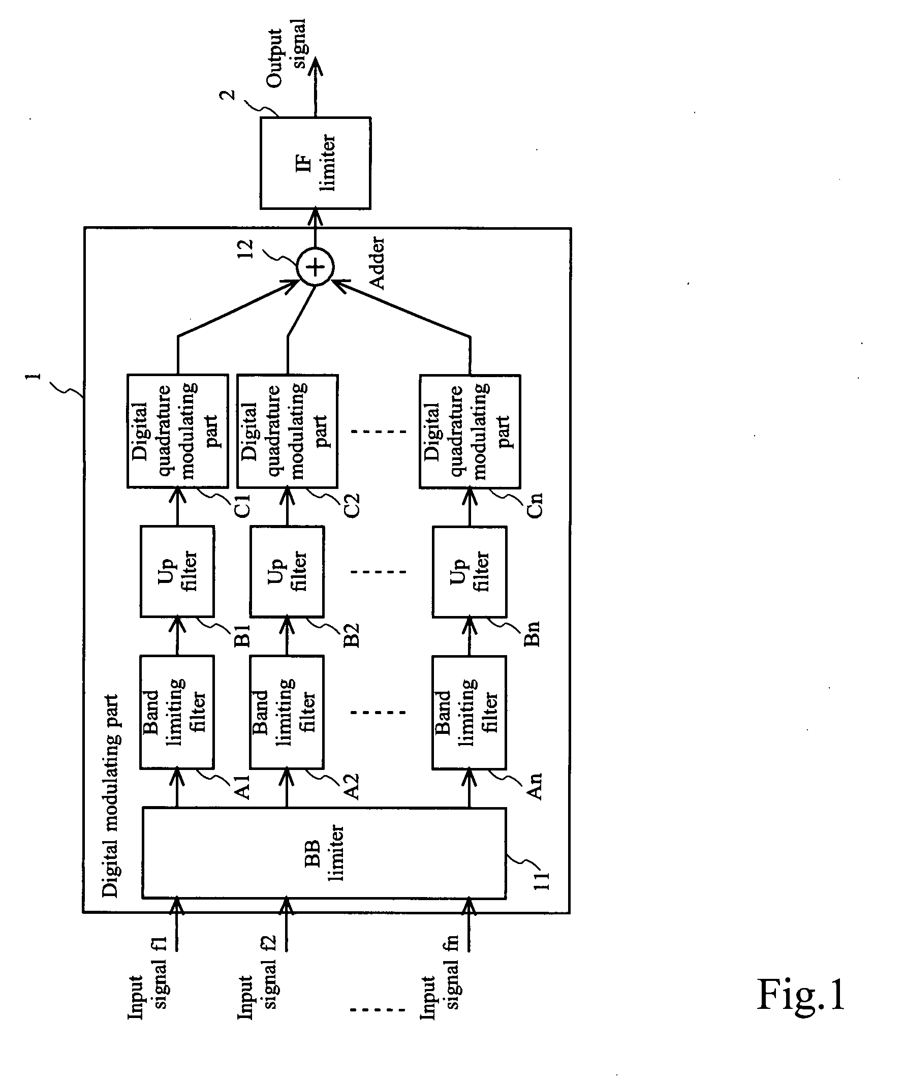
[0049]FIG. 1 shows an exemplary configuration of a transmitter according to the first embodiment of the invention.

[0050] The transmitter according to the embodiment has a digital modulating part 1, and an intermediate frequency (IF: Intermediate Frequency) limiter 2.

[0051] The digital modulating part 1 has a baseband (BB: BaseBand) limiter 11 on the input side and an adder 12 on the output side, and has n paths of signal processing paths therebetween as corresponding to a plurality of n of carriers.

[0052] The signal processing paths have band limiting filters A1 to An, up filters (Up filter) B1 to Bn, and digital quadrature modulating parts C1 to Cn, each path has each one of them.

[0053] An exemplary operation performed by the transmitter according to the embodiment is shown.

[0054] In the embodiment, baseband signals each corresponding to n of carriers having frequencies f1 to fn different from each other are inputte...

embodiment 2

[0119] A second embodiment of the invention will be described.

[0120]FIG. 4 shows an exemplary configuration of a transmitting amplifier according to an embodiment of the invention.

[0121] The transmitting amplifier according to the embodiment has the configuration of a transmitter formed of a digital modulating part 1 and an IF limiter 2 as similar to that shown in FIG. 1. In the subsequent stage of the IF limiter 2, a DPD (Digital Pre-Distortion) part 44, a D / A converter 41, a frequency converting part 42, and a power amplifier (PA) 43 are provided.

[0122] Moreover, in the embodiment, the portion of the configuration of the transmitter formed of the digital modulating part 1 and the IF limiter 2 is the same as that of FIG. 1, omitting the descriptions using the same numerals and signs.

[0123] An exemplary operation performed by the transmitting amplifier according to the embodiment is shown.

[0124] The DPD part 44 receives an IF signal that is processed by the digital modulating p...

embodiment 3

[0142] This embodiment is that the invention is adapted to a transmitter which is mounted on a base station unit, for example, in the radio communication system adapting the CDMA mode. In such a transmitter, generally, high power signal amplification is performed by an amplifier. Moreover, the amount to suppress the peak level is sometimes restrained, but for example, the invention may be adapted to the modulation mode such as OFDM as well.

[0143] The embodiment is different from the embodiments 1 and 2 in that a peak suppression coefficient that is newly generated is made small depending on the degree of overlapping with the peak suppression coefficient that has been generated in the past.

[0144]FIG. 7 shows a diagram depicting an exemplary configuration of a transmitter according to the embodiment.

[0145] To the transmitter according to the embodiment, n of code multiplexed signal generating parts 5A to 5N are connected as corresponding to a plurality of n of carriers A to N.

[014...


PUM


Abstract

A transmitter is provided which effectively reduces a peak that occurs in transmitting signal electric power. A baseband limiter means 11 applies a peak reduction process to digital signals to be a transmission target on a plurality of carriers in a baseband. Band limiting filter means A1 to An apply a band limitation process to the digital signals on each of the carriers to which the peak reduction process is applied. Quadrature modulation processing means C1 to Cn apply a quadrature modulation process to the digital signals on each of the carriers to which the band limitation process is applied. An adding means 12 adds the digital signals on each of the carriers to which the quadrature modulation process is applied. An intermediate frequency limiter means 2 multiplies a signal of the added result by a window function that is weighted depending on the magnitude of the detected peak, and applies a peak reduction process thereto. At this time, when a plurality of peak reduction processes is overlapped with each other, a weight of the subsequent window function is made small to prevent excessive suppression.

Description

TECHNICAL FIELD [0001] The present invention relates to a transmitter for use in a mobile communication system and the like, particularly to a transmitter which effectively reduces peak electric power that occurs in a transmitting signal. BACKGROUND ART [0002] For example, in a transmitter for a mobile communication system which adopts the code division multiple access communication (CDMA: Code Division Multiple Access) mode and the like for radio communications, a signal to be a transmission target (transmitting signal) is processed by a digital modulating part. [0003]FIG. 6 shows an exemplary configuration of a transmitting amplifier. [0004] In a digital modulating part 51 in this example, signals on a plurality of n of carriers are inputted to a baseband limiter (BB limiter) 61, the signals on the carriers outputted from the BB limiter 61 pass through band limiting filters F1 to Fn, up filters (Up filters) G1 to Gn and digital quadrature modulating parts H1 to Hn, they are added ...

Claims


Application Information

Patent Timeline
IPC IPC(8): H04L27/20H04B1/707
CPCH04B1/0475H04L27/2624H04L5/06H04B2201/70706
Inventor OKADA, TAKASHIABE, TATSUYA
Owner KOKUSA ELECTRIC CO LTD
Why Eureka
Try Eureka