Al technical title is built by PatSnap Al team. It summarizes the technical point description of the patent document.
a power system and zero emission technology, applied in the direction of machines/engines, liquefaction, lighting and heating apparatus, etc., can solve the problems of reducing the useful life of equipment, enhancing the potential for increased maintenance, and emitted pollution from fuel combustion based steam power plants
Inactive Publication Date: 2007-09-06
CLEAN ENERGY SYST
View PDF5 Cites 48 Cited by
Summary
Abstract
Description
Claims
Application Information
AI Technical Summary
This helps you quickly interpret patents by identifying the three key elements:
Problems solved by technology
Method used
Benefits of technology
[0013] Another object of the present invention is to provide a zero emissions power generation system which uses the well known closed Rankine cycle, for reliability and ease of construction and operation.
[0015] Another object of the present invention is to provide a zero emissions power generation system which can be used to retrofit an existing steam power plant with minimal modification of the power plant required.
Problems solved by technology
Heretofore, fuel combustion based steam power plants have emitted pollution due to the products of combustion of the fuel being too difficult to capture or neutralize entirely, in an economic fashion, and so requiring release.
One source of equipment wear is corrosion.
However, the working fluid of such prior art zero emissions power plants has been a combination of CO2 and water.
Also, because the heating is “internal,” any other pollutants in the products of combustion pass through the turbine, and other equipment in the plant, enhancing the potential for increased maintenance and decreased useful life.
Method used
Image
Click on the blue label to locate the original text in one second.
Reading with bidirectional positioning of images and text.
Examples
Embodiment Construction
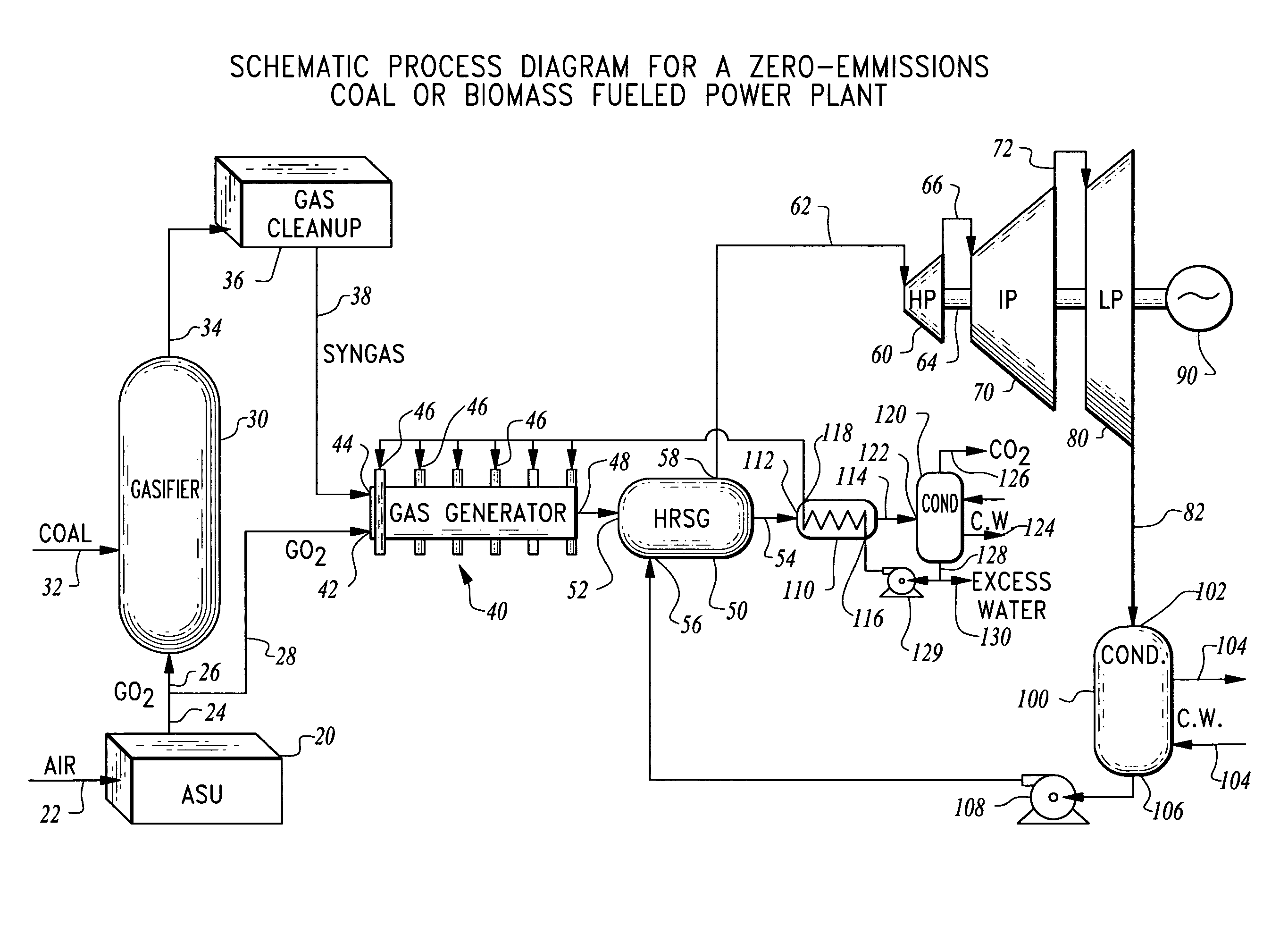
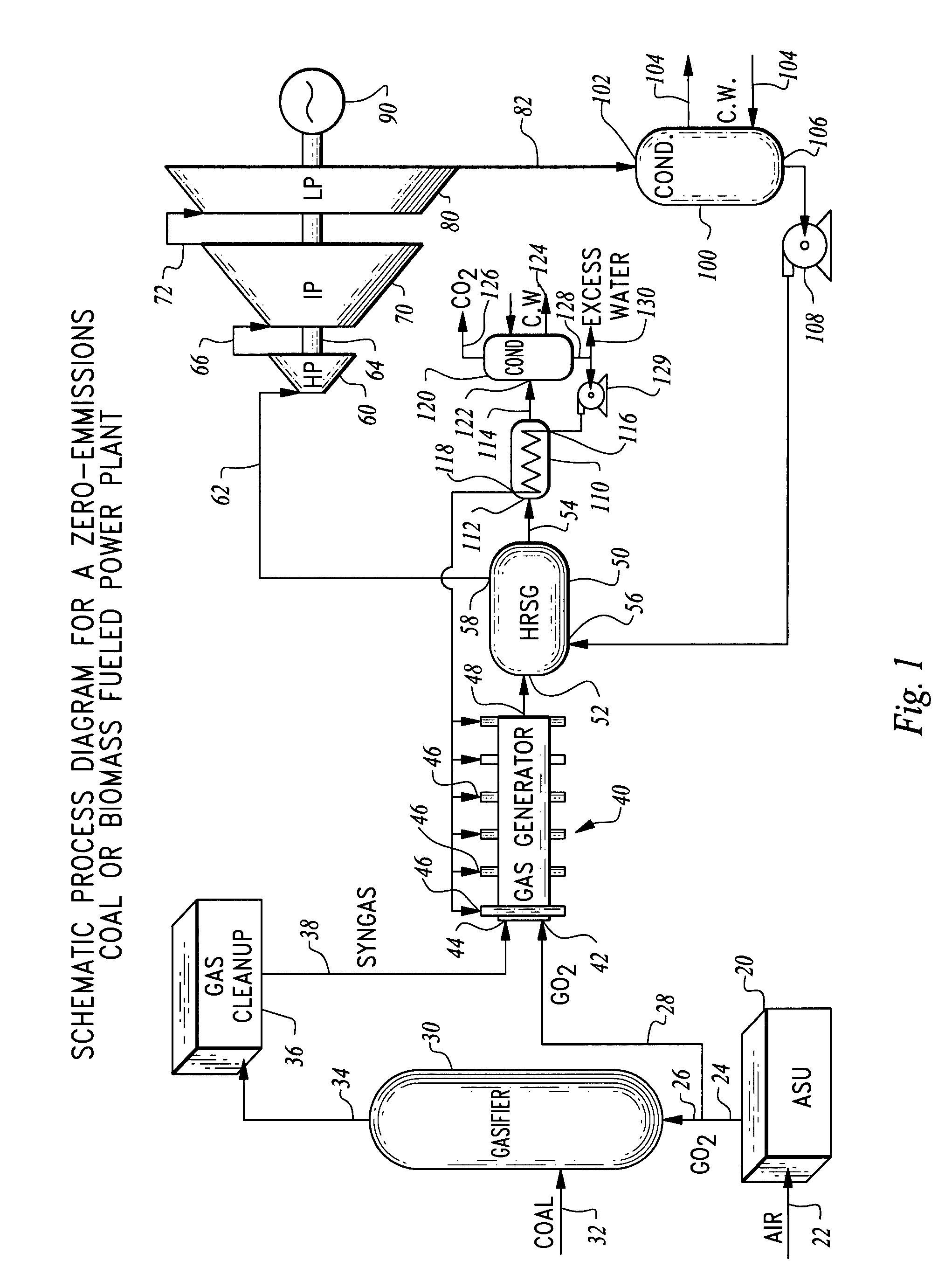
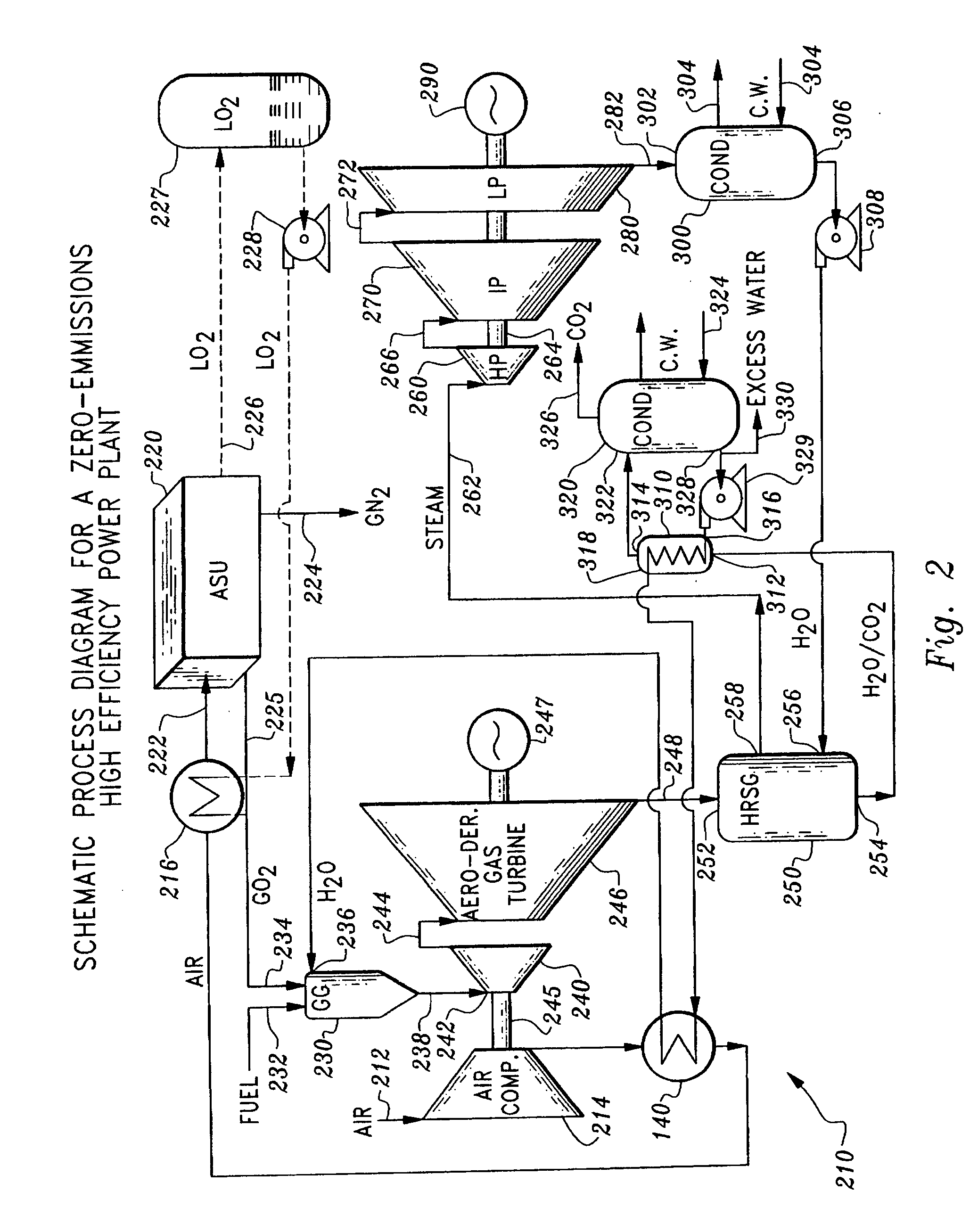
[0020] Referring to the drawings, wherein like reference numerals represent like parts throughout the various drawing figures, reference numerals 10, 210 and 410 (FIGS. 1, 2 and 3, respectively) are directed to variations on a zero emissions power generation system according to this invention. The fuel is combusted with a majority oxygen oxidizer, so that products of combustion, typically steam and CO2, result in volumes that can be readily separated and handled without atmospheric release.
[0021] In essence, and with particular reference to FIG. 1, a basic form of this invention is described. While FIG. 1 particularly discloses a coal fueled power plant, a most basic form of this invention would operate on a fuel that is ready to combust without requiring gasification. Thus in such a most basic system the gasifier 30 and gas cleanup 36 of FIG. 1 would be replaced with a source of fuel, such as gaseous methane (“natural gas”). Also, a most basic form of this invention could receive ...
PUM
Abstract
A fuel combustion power generation system is provided operating as a closed loop Rankine cycle and with zero atmospheric emissions. The fuel is combusted with oxygen in a combustor to generate high temperature products of combustion. The products of combustion are routed to a first side of a heat exchanger. A second side of the heat exchanger has a working fluid of the closed loop Rankine cycle passed therethrough to boil the working fluid into a gas. The working fluid is then expanded, condensed back to a liquid and pumped back to high pressure for return to the heat exchanger the products of combustion enter a condenser, where gases are collected and liquids recirculated or released. The products of combustion can be expanded upstream of the heat exchanger. The fuel can be a gaseous fuel or a solid or liquid fuel, such as coal or biomass, with gasification before combustion.
Description
CROSS-REFERENCE TO RELATED APPLICATIONS [0001] This application is a divisional of U.S. patent application No. 11 / 109,237, filed on Apr. 18, 2005. This application claims benefit under Title 35, United States Code § 119(e) of United States Provisional Application Nos. 60 / 562,775, 60 / 562,792 and 60 / 562,776 filed on Apr. 16, 2004. This application also incorporates by reference the entire contents of U.S. Pat. Nos. 5,447,555; 5,611,219; 6,598,398; 5,956,937; 6,206,684; 6,637,183; and 6,868,677. FIELD OF THE INVENTION [0002] The following invention relates to power generation systems which generate power by combustion of a fuel with an oxidizer, and expanding the products of combustion to output power. More particularly, this invention relates to power systems which utilize a majority oxygen oxidizer to combust the fuel, so that little or no pollutants are generated, and which transfer heat externally though a heat exchanger from the products of combustion to a working fluid within a c...
Claims
Application Information
Patent Timeline
Application Date:The date an application was filed.
Publication Date:The date a patent or application was officially published.
First Publication Date:The earliest publication date of a patent with the same application number.
Issue Date:Publication date of the patent grant document.
PCT Entry Date:The Entry date of PCT National Phase.
Estimated Expiry Date:The statutory expiry date of a patent right according to the Patent Law, and it is the longest term of protection that the patent right can achieve without the termination of the patent right due to other reasons(Term extension factor has been taken into account ).
Invalid Date:Actual expiry date is based on effective date or publication date of legal transaction data of invalid patent.
Patent Type & Authority Applications(United States)