Double-effect thermoelectric cooling apparatus

a thermoelectric cooling and thermoelectric technology, applied in the direction of domestic cooling apparatus, lighting and heating apparatus, machine operation mode, etc., can solve the problems of increasing the operating temperature, increasing the power consumption of semiconductors, and complicated electrical circuit layout of semiconductors, so as to reduce the operating temperature of semiconductors, increase the operation stability of computers, and reduce the temperature inside the computer.

Inactive Publication Date: 2007-09-06
CHANNEL WELL TECH
View PDF6 Cites 23 Cited by
  • Summary
  • Abstract
  • Description
  • Claims
  • Application Information

AI Technical Summary

Benefits of technology

[0013]The double-effect thermoelectric cooling apparatus according to the present invention can use a cooling fan to suck external air into the computer to cool a part of the air by the thermoelectric chip-cooling module. The cold air can be directly driven to a heat source, for example, an integrated circuit such as a central processing unit or a graphic chip, to reduce the operating temperature thereof. In addition, another part of the air is driven to the hot side of the thermoelectric chip-cooling module with the same fan to remove the heat exchanged by the thermoelectric chip-cooling module. Accordingly, the double-effect thermoelectric cooling apparatus can effectively reduce the temperature inside the computer and increase the operation stability of the computer.

Problems solved by technology

Therefore, the electric circuit layouts of semiconductors have become more complicated and more sophisticated.
Complicated and sophisticated semiconductors have higher power consumption, which results in an increase in the operating temperature thereof.
The high operating temperature can cause instabilities in a working system.
Furthermore, if the operating temperature is too high, the performance and stability decrease and the operating system may even crash, in extreme situations.
However, when the heat generated by the CPU is removed from the CPU, the heat still resides in the computer.
The larger heat-dissipating device has to occupy more space inside the computer otherwise the stability of the computer system may be reduced because there is too much heat inside the computer.

Method used


Image

  • Double-effect thermoelectric cooling apparatus
  • Double-effect thermoelectric cooling apparatus

Examples


Embodiment Construction

[0016]The following description is of the best presently contemplated mode of carrying out the present invention. This description is not to be taken in a limiting sense but is made merely for the purpose of describing the general principles of the invention. The scope of the invention should be determined by referencing the appended claims.

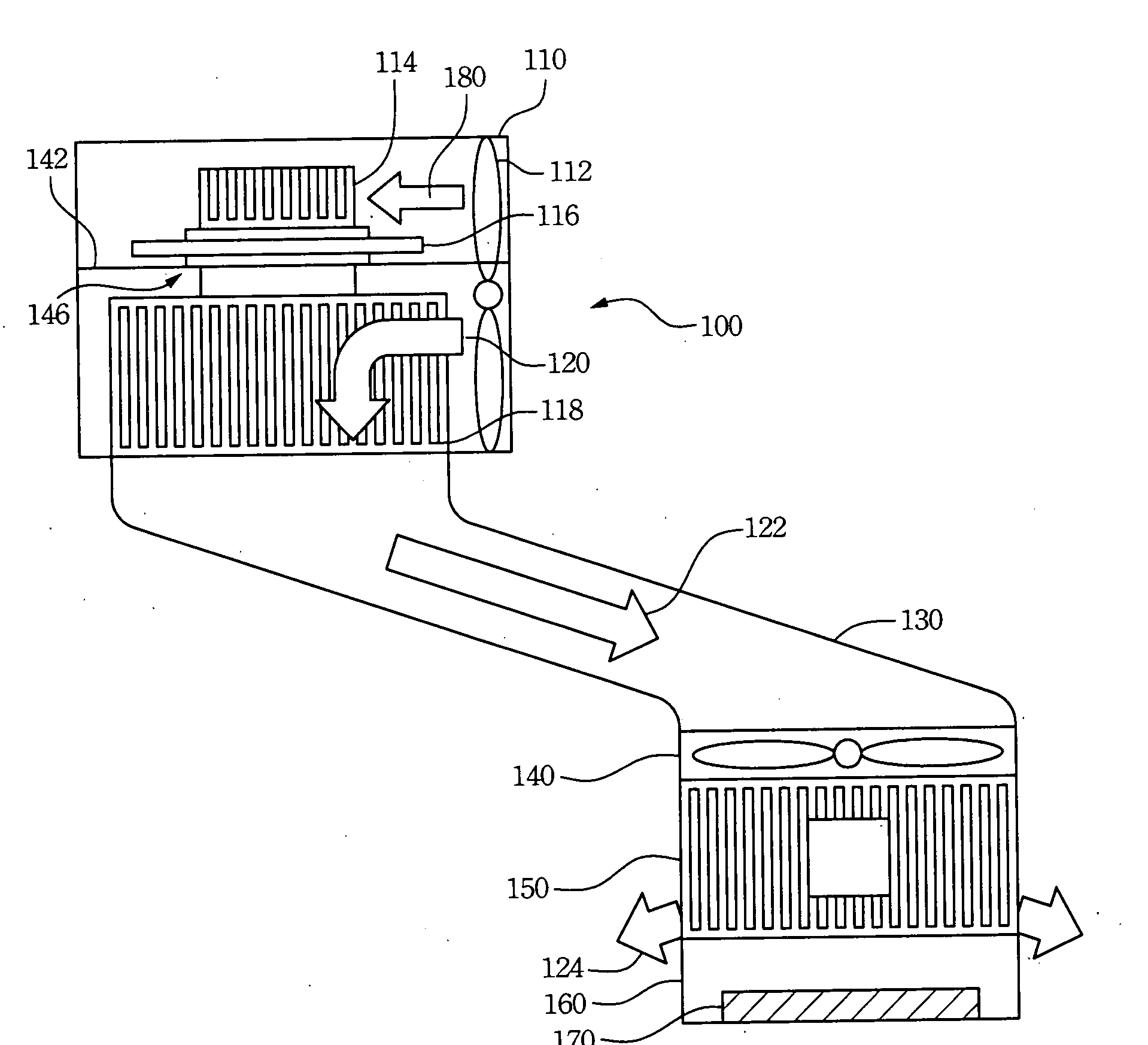
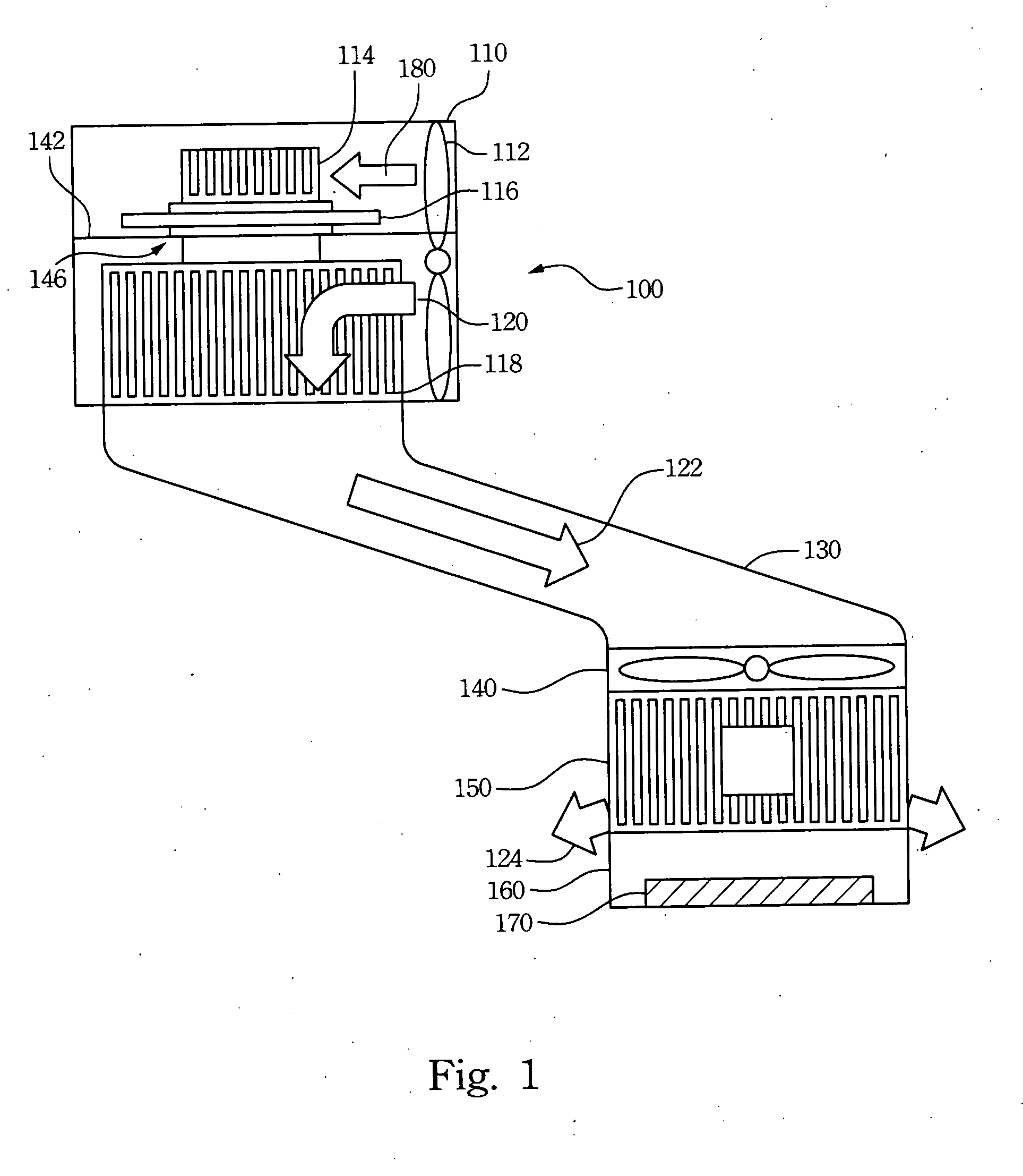
[0017]Refer to FIG. 1. FIG. 1 illustrates an embodiment of a double-effect thermoelectric cooling apparatus according to the present invention. The double-effect thermoelectric cooling apparatus 100 includes a fan 112, heat-dissipating fins 114, a thermoelectric chip-cooling module 116, cooling fins 118 and a wind guide 130. The heat-dissipating fins 114 and the thermoelectric chip-cooling module 116 are disposed inside the heat-dissipating barrel 110, and the fan 112 drives air 180 from the outside of the heat-dissipating barrel 110 to the heat-dissipating fins 114 to remove the heat exchanged by the thermoelectric chip-cooling module 116. The f...


PUM


Abstract

A double-effect thermoelectric cooling apparatus is described. The double-effect thermoelectric cooling apparatus includes a heat-dissipating barrel, a wind guide, cooling fins, and a fan. The heat-dissipating barrel further includes a thermoelectric chip-cooling module and heat-dissipating fins disposed therein. The fan drives a part of air passing through the heat-dissipating fins to remove a heat exchanged by the thermoelectric chip-cooling module. One end of the wind guide is coupled to a heat source of an electronic device, for example, a CPU or a graphic card of a computer. Another end of the wind guide is coupled to the fan to guide another part of the air through the cooling fins reducing the temperature thereof to the heat source of the electronic device to reduce the operating temperature of the heat source.

Description

RELATED APPLICATIONS[0001]The present application is based on, and claims priority from, Taiwan Application Serial Number 95203660, filed Mar. 6, 2006, the disclosure of which is hereby incorporated by reference herein in its entirety.FIELD OF THE INVENTION[0002]The present invention generally relates to a double-effect thermoelectric cooling apparatus. More particularly, this invention relates to a double-effect thermoelectric cooling apparatus for a computer system.BACKGROUND OF THE INVENTION[0003]The information technology and the computer industry are technologically highly developed and the semiconductor manufacturing processes have very advanced requirements. Therefore, the electric circuit layouts of semiconductors have become more complicated and more sophisticated. Complicated and sophisticated semiconductors have higher power consumption, which results in an increase in the operating temperature thereof.[0004]However, semiconductor electronic components are used extensivel...

Claims


Application Information

Patent Timeline
Patent Type & Authority Applications(United States)
IPC IPC(8): F25B21/02F25D23/12F25B7/00
CPCF25B21/02F25B2321/0251H01L23/38H01L2924/0002H01L2924/00
Inventor PAN, CHUN-WEI
Owner CHANNEL WELL TECH
Why Eureka
Try Eureka