[0008] Therefore, with the above problem of the prior art in view, it is an object of the present invention to provide an apparatus (hereinafter, referred to as a “detecting apparatus”) for detecting a concentration and a remaining amount of a liquid reducing agent by calculating the concentration of the liquid reducing agent only when a vehicle state is stable without vibrating while determining the remaining amount of the liquid reducing agent irrespective of the vehicle state, to thereby ensure accuracy in detection of both the concentration and the remaining amount of the liquid reducing agent.
[0010] Here, because the
convection of the liquid reducing agent that occurs immediately after the stop of the vehicle is closely related to the deceleration, it is possible to determine the vehicle state with high accuracy by dynamically setting the determination time period depending on the deceleration of the vehicle.
[0011] It is also possible to successively sum up given points in response to the result of determination of the remaining amount of the liquid reducing agent based on the signal from the sensor and to determine that the liquid reducing agent has been used up when the sum of the points becomes equal to or greater than a predetermined value. In this way, even if it is determined that the remaining amount is reduced to “zero” based on the signal from the sensor, this determination is not immediately reflected on determination result of the remaining amount. Namely, the points are gradually added, and when the sum of the points becomes equal to or greater than the predetermined value, it is determined for the first time that the remaining amount reaches “zero”. Therefore, even if
noise or the like is superimposed on the signal from the sensor, erroneous determination can be avoided to thereby substantially increase the determination accuracy of the remaining amount of the liquid reducing agent. At this time point, the points may be written in a nonvolatile memory when the engine stops and then the points may be read out of the memory when the engine starts, so as to take over the points which are summed before the start of the engine. Therefore, it becomes unnecessary to renew the points from the start every time the engine is started and it is possible to determine the remaining amount of the liquid reducing agent with high accuracy even immediately after the start of the engine.
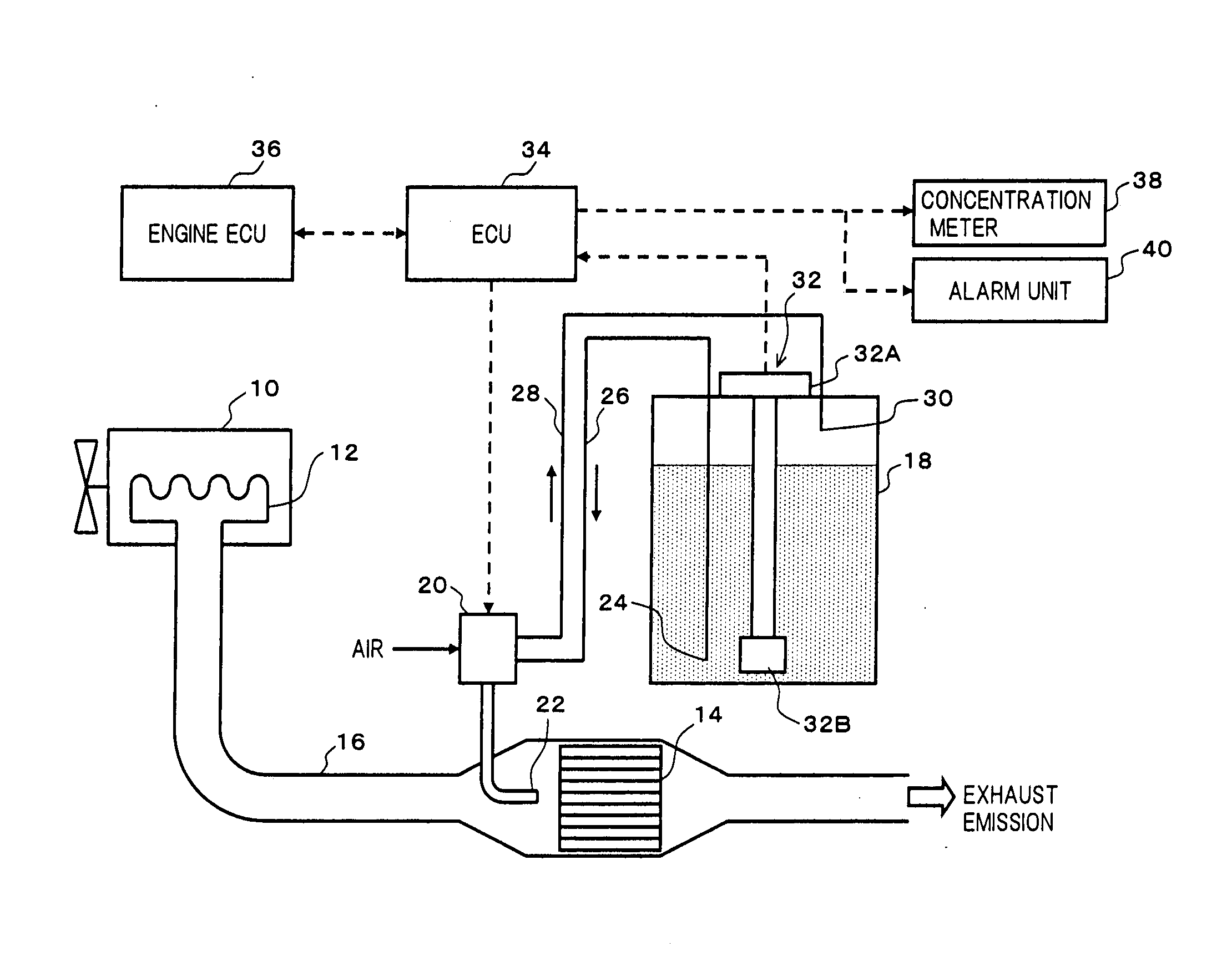
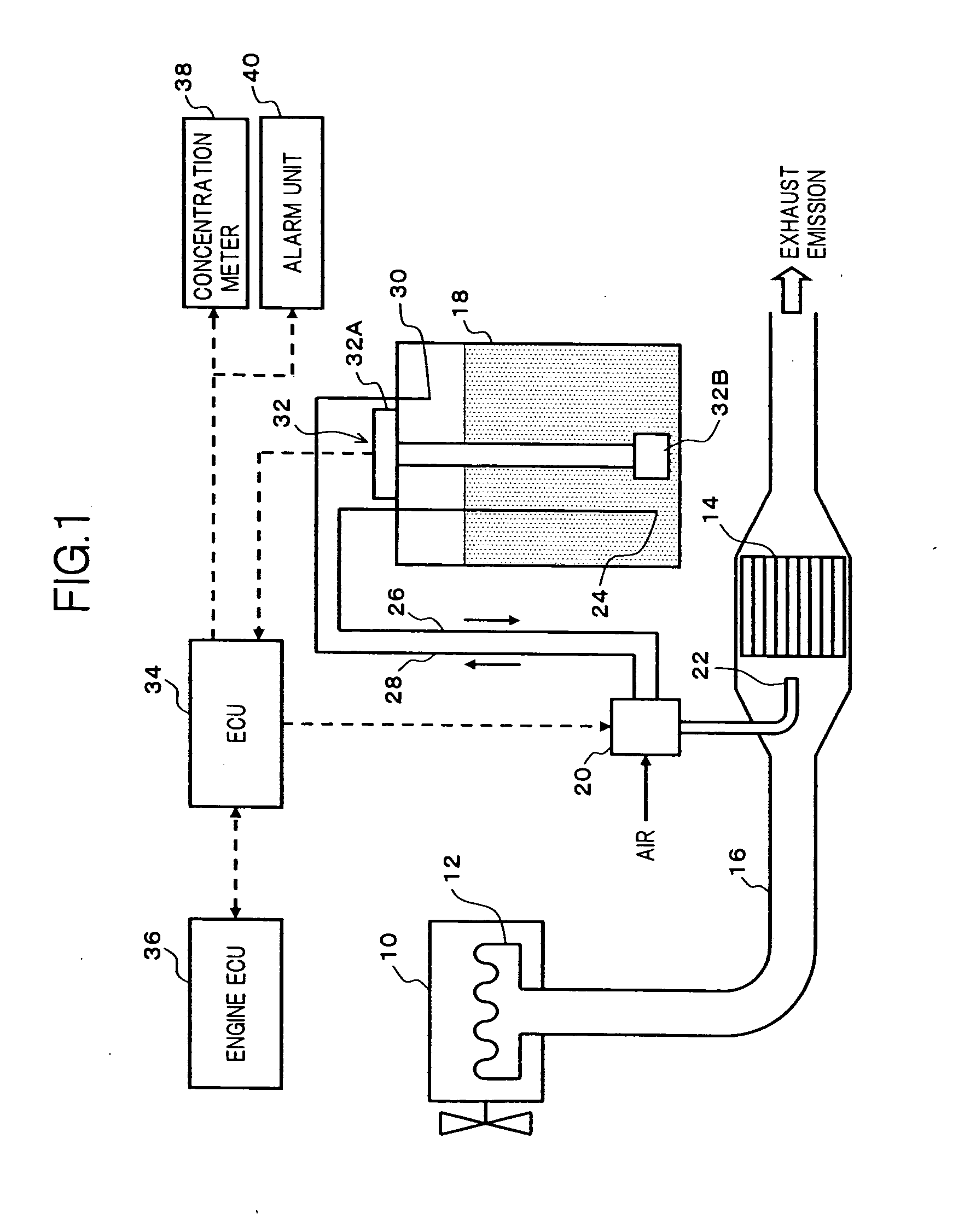
[0012] Furthermore, there may be provided a concentration data-storing unit for storing concentration data of the liquid reducing agent, which stores the concentration data of liquid reducing agent in a manner such that the stored concentration data can be renewed by a lately calculated concentration of liquid reducing agent. In this way, it is possible to refer to the concentration data of the liquid reducing agent at any time. A concentration indicating unit for visually indicating the stored concentration data of the liquid reducing agent or a first annunciating unit for giving a notice that the concentration deviates from a predetermined range when it happens may be provided. Hence, it is possible to maintain the concentration of the liquid reducing agent within the predetermined range by properly carrying out operations such as replenishing the
storage tank with the liquid reducing agent, in response to the indication or the operation of giving a notice.
[0013] Moreover, there may be provided a remaining amount data-storing unit for storing data of the remaining amount of liquid reducing agent, which stores therein the data of the remaining amount of liquid reducing agent in a manner such that the stored data can be renewed by a determination result of the remaining amount of liquid reducing agent. In this way, it is possible to refer to the data of the remaining amount of the liquid reducing agent at any time. A second annunciating unit for giving a notice that the remaining amount of the liquid reducing agent becomes zero when it happens may be provided. Hence, it is possible to prevent
continuation of the engine operation without liquid reducing agent by properly replenishing the
storage tank with the liquid reducing agent in response to the operation of giving a notice.
[0014] With the present invention, if the
stationary state of the vehicle lasts for the predetermined determination time after the vehicle has been stopped, it is determined that the vehicle state is stable. In other words, during driving or deceleration of the vehicle, acceleration acts in multiple directions on the liquid reducing agent in the storage tank to generate
convection. However, when the vehicle stops, the
convection in the liquid reducing agent gradually decreases with the elapse of time and finally disappears. Therefore, in addition to determining whether or not the vehicle is stopped, by determining whether or not the stopping state lasts for the determination time, it is possible to indirectly know that the convection has disappeared in the liquid reducing agent in the storage tank with high accuracy. When the measurement trigger is output and the vehicle state is stable, the concentration of the liquid reducing agent is calculated based on the signal from the sensor. On the other hand, every moment of time the measurement trigger is output, the remaining amount of the liquid reducing agent is determined based on the signal from the sensor.

